Distal radius bone plating system with locking and non-locking screws

a plating system and distal radius technology, applied in the field of bone plating system and bone fixation method, can solve the problems of screw head size, plate hole too large to catch screw head, screw head impracticality, etc., and achieve the effect of maximizing the benefi

Active Publication Date: 2006-11-21
WRIGHT MEDICAL TECH
View PDF18 Cites 141 Cited by
  • Summary
  • Abstract
  • Description
  • Claims
  • Application Information

AI Technical Summary

Benefits of technology

[0011]In using the bone plating system of the present invention, to maximize the benefit of combining non-locking bone screws with locking bone screws, both the locking and non-locking bone screws remain seated in their respective plate holes for substantially as long as the bone plate is implanted.

Problems solved by technology

If the non-threaded plate hole were to be made large enough to completely clear the cancellous thread of the cancellous bone screw, the plate hole would be too large to catch the screw head.
Also, making the head of the screw larger would make the screw head impractical, and be counter to the long established goal of size reduction for in vitro devices used in minimally invasive surgical procedures.

Method used


Image

  • Distal radius bone plating system with locking and non-locking screws
  • Distal radius bone plating system with locking and non-locking screws
  • Distal radius bone plating system with locking and non-locking screws

Examples


Embodiment Construction

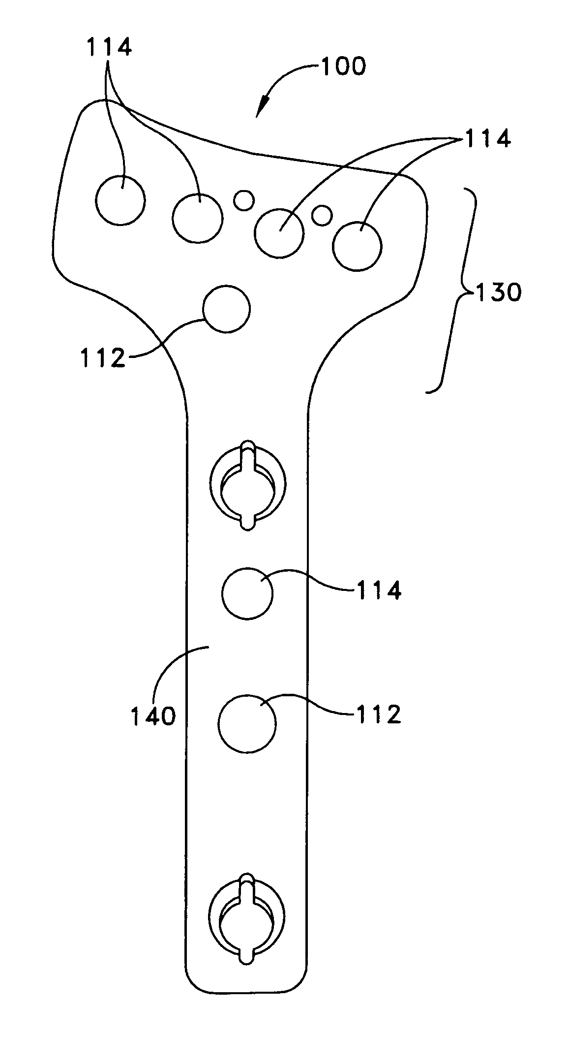
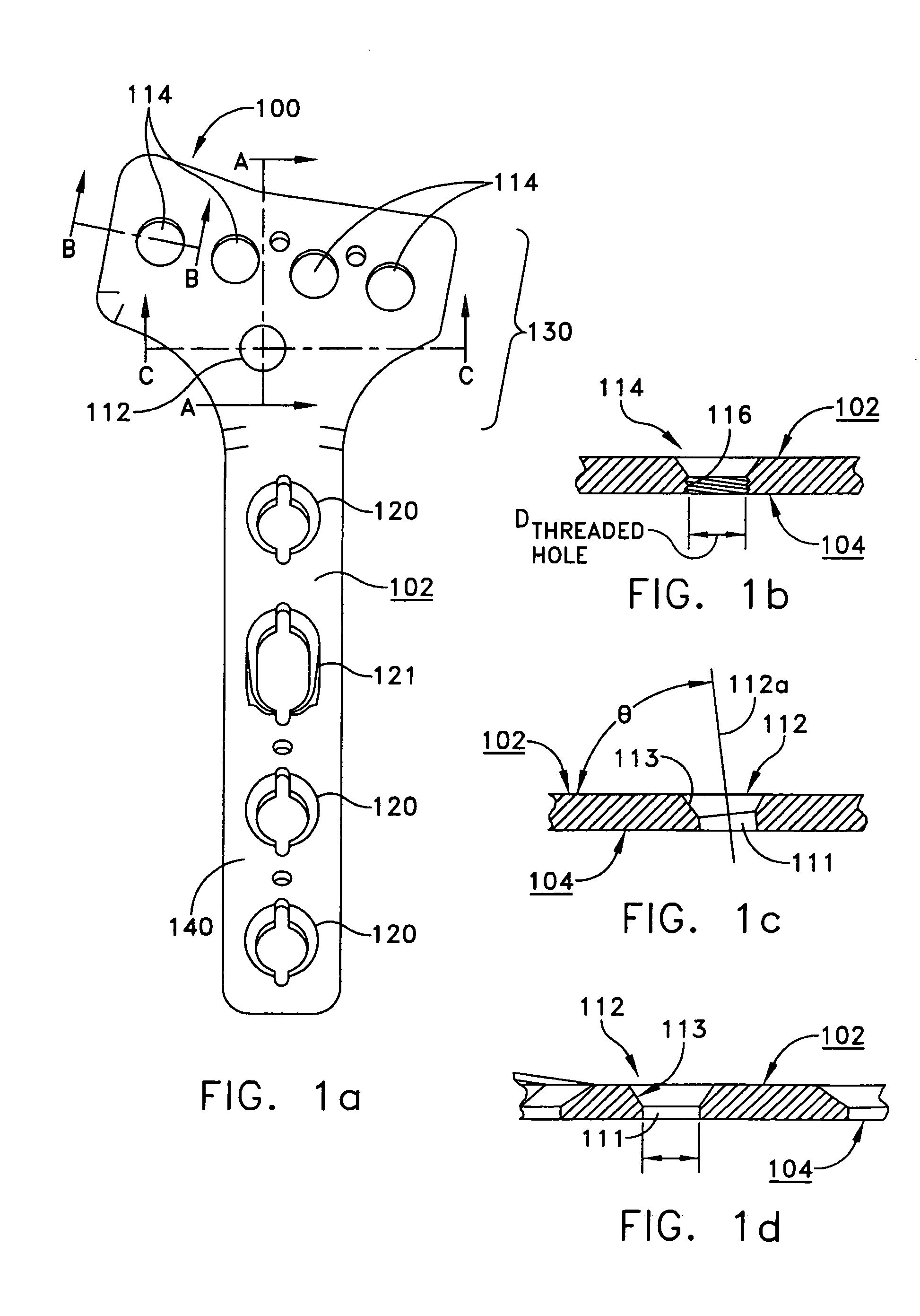
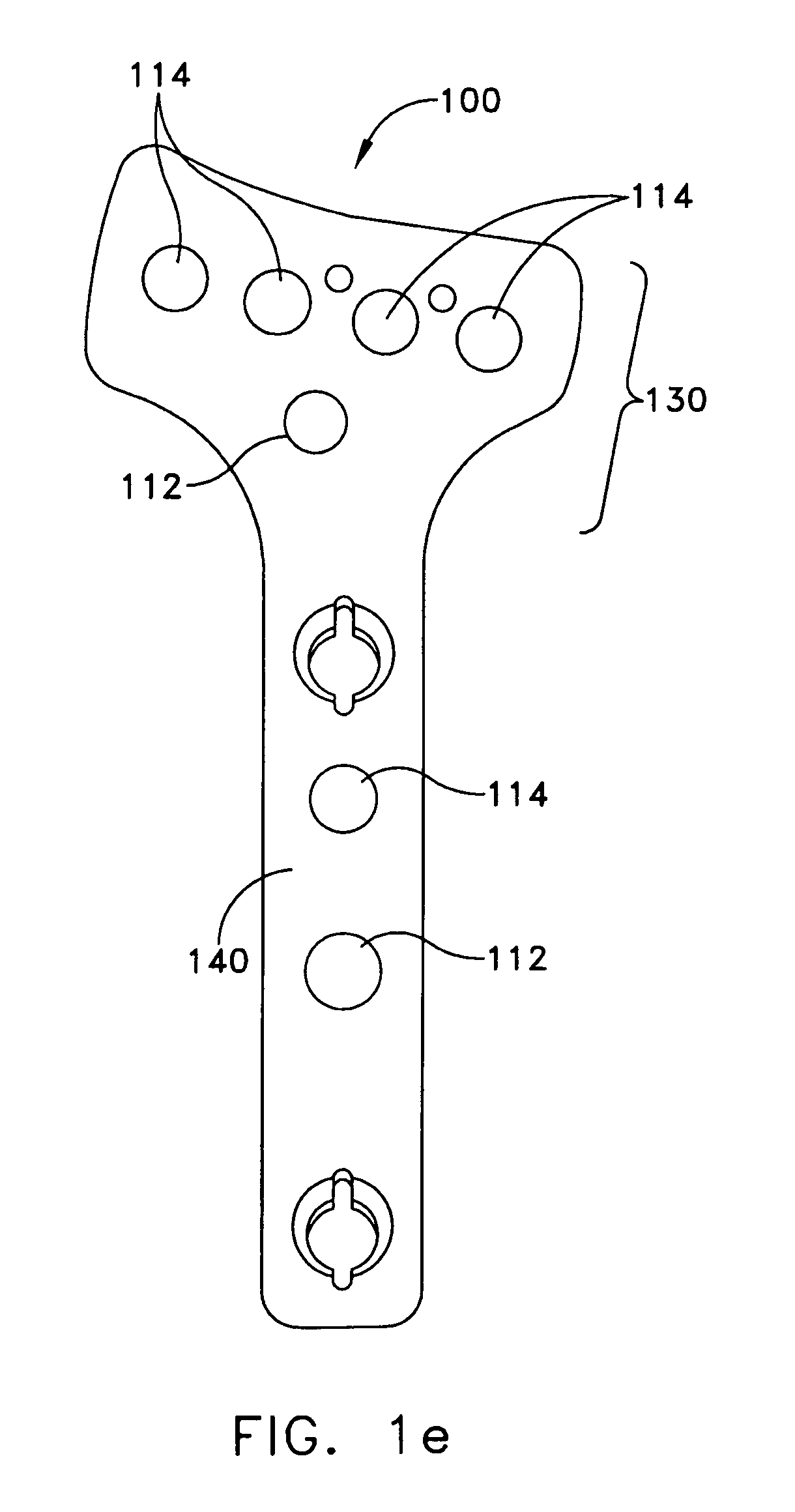
[0030]Bone plating system formed in accordance with one embodiment of the invention includes a bone plate, locking bone screws, and non-locking bone screws. FIGS. 1a through 4 show an exemplary bone plate 100 according to an aspect of the present invention designed for use in the distal radius volar region. Bone plate 100 has an upper surface 102, a lower surface 104, which is generally the bone-contacting surface, a head portion 130, and a shaft portion 140.

[0031]Bone plate 100 has a plurality of plate holes for receiving bone screws in both head portion 130 and shaft portion 140. The plate holes in head portion 130 comprise threaded plate holes 114 for receiving locking bone screws 10. As shown in FIG. 1b, each of threaded plate holes 114 has a diameter Dthreaded-hole, a thread 116 on the sidewall of bone plate 100 that defines threaded plate holes 114 for mating with a locking bone screw 10 (shown in FIG. 5). At least one of the plate holes in head portion 130, however, is a non-...


PUM


Abstract

A bone plating system for fixating distal or proximal ends of long bones includes a bone plate having a head portion and a shaft portion, and a plurality of bone screws, at least one of which is a locking bone screw and at least one non-locking cancellous bone screw. The bone plate has a plurality of plate holes in the head portion and a plurality of plate holes in the shaft portion. The head portion or the shaft portion of the bone plate may have a plurality of threaded plate holes for engaging the at least one locking bone screw and at least one non-threaded plate hole for engaging the non-locking cancellous bone screw. The non-locking cancellous bone screw and the at least one non-threaded plate hole are configured and dimensioned to have a particularly useful dimensional relationship.

Description

FIELD OF THE INVENTION[0001]The present invention relates to a bone plating system and method for fracture fixation of bone.BACKGROUND[0002]For bone fractures such as peri-articular fractures, bone plating systems that provide fixed angular relationship between the bone plate and the bone screw are known to be beneficial. Many of these devices require suitable bone quantity and quality, and a fracture pattern that is compatible with the device to be effective. Where these requirements are not satisfied, e.g. bone fractures involving severely comminuted bone or missing bone segments, conventional bone plate and screw systems must be used. Although these conventional systems are particularly well-suited to promoting healing of the fracture by compressing the fracture ends together and drawing the bone into close apposition with other fragments and the bone plate, the angular relationships between the plate and screws are not fixed and can change postoperatively. This can lead to malal...

Claims


Application Information

Patent Timeline
Patent Type & Authority Patents(United States)
IPC IPC(8): A61B17/58
CPCA61B17/8057A61B17/8061Y10S606/906
Inventor PATTERSON, CHAD J.BAYS, F. BARRYROBERTS, JEFFREY G.
Owner WRIGHT MEDICAL TECH
Why Eureka
Try Eureka