
Apparatus and method for the removal of solids and floatables from a wastewater stream

Active Publication Date: 2006-11-21
CH2M HILL
View PDF36 Cites 33 Cited by
  • Summary
  • Abstract
  • Description
  • Claims
  • Application Information

AI Technical Summary

Benefits of technology

[0011]In one embodiment, a pivotal connection is provided between the grating and the chamber floor which enables variation of the vertical incline of the grating between about 30 degrees to greater than 85 degrees from horizontal. When pivoted to a more vertical orientation, the grating may be backwashed for cleaning purposes. A one way check valve may be operatively associated with the outlet to prevent backflow into the wastewater outlet.
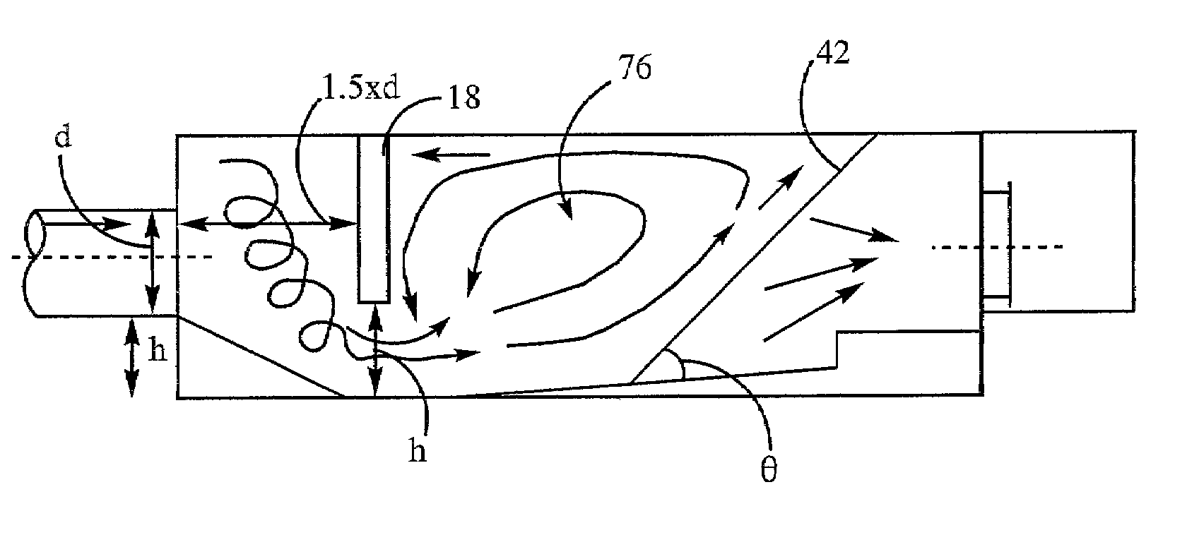
[0013]The apparatus for removing solids and floatables from a wastewater stream in accordance with the present invention provides a system which effectively self-cleans the screen during a storm event to allow for the efficient flow of wastewater through the solids removal facility. The apparatus creates a vortex which tends to suspend particulates, particularly high volume floatable particulates, by imparting a force along the grating directed toward the wastewater surface on the particulates trapped by the grating. Among the advantages this system provides is elimination of the need to have the removal facility continuously manned during a storm event to prevent blockage. The apparatus can also be installed below grade and effectively concealed from view, meaning that its use will not degrade the aesthetic appeal of the waterway shore. When desirable to clean the apparatus, the grating can be pivoted to be substantially vertical to facilitate effective backwashing of the grating to remove trapped solids. Provision of screening chambers in parallel allows for flow to be diverted from a select screen chamber during cleaning and maintenance. This feature enhances safety for the maintenance personnel.

Problems solved by technology

However, particularly in urban areas, this wastewater is likely to entrain relatively innocuous particulate materials, such as sand, gravel and potentially more objectionable particulates such as hypodermic needles and all manner of garbage.
This can result in the discharge of highly undesirable debris into natural waterways.
The problem described above is exasperated in those areas having combined wastewater and sewage conveying systems.
However, when exceptional storm events occur, sewage treatment plants can become overwhelmed and it is necessary to release combined and untreated wastewater and sewage to natural waterways.
This mesh bag technology has several serious deficiencies.
First, debris collected in the bag can create significant headloss by limiting the cross-sectional flow area and creating additional force upon the bag.
If sufficient force is developed, this can damage the bag or otherwise result in a release of unacceptable solid and floatable materials to the natural waterway.
Second, the nets are also unsightly and can lead to odor problems.
Third, rodent activity, prevalent in sewer and conveying systems, can create tears in the bags that would result in a release of unacceptable solid and floatable materials to the natural waterway.
The disposable bag also exacerbates waste disposal issues.
However, known screening systems have a problem with debris buildup that can obstruct the flow of wastewater through the screening system during a storm event.
This can lead to serious problems, including sewage backups in the conveying system that can result in the undesired discharge of unscreened wastewater through upstream catch basins and manholes to the natural waterway.
While suitable for the removal of these cleaning particles for reuse, such a system is not effective for wastewater solids removal because of the difficulty in continuously extracting solids of non-uniform size and shape likely to be encountered in wastewater runoff.

Method used


Image

  • Apparatus and method for the removal of solids and floatables from a wastewater stream
  • Apparatus and method for the removal of solids and floatables from a wastewater stream
  • Apparatus and method for the removal of solids and floatables from a wastewater stream

Examples


Embodiment Construction

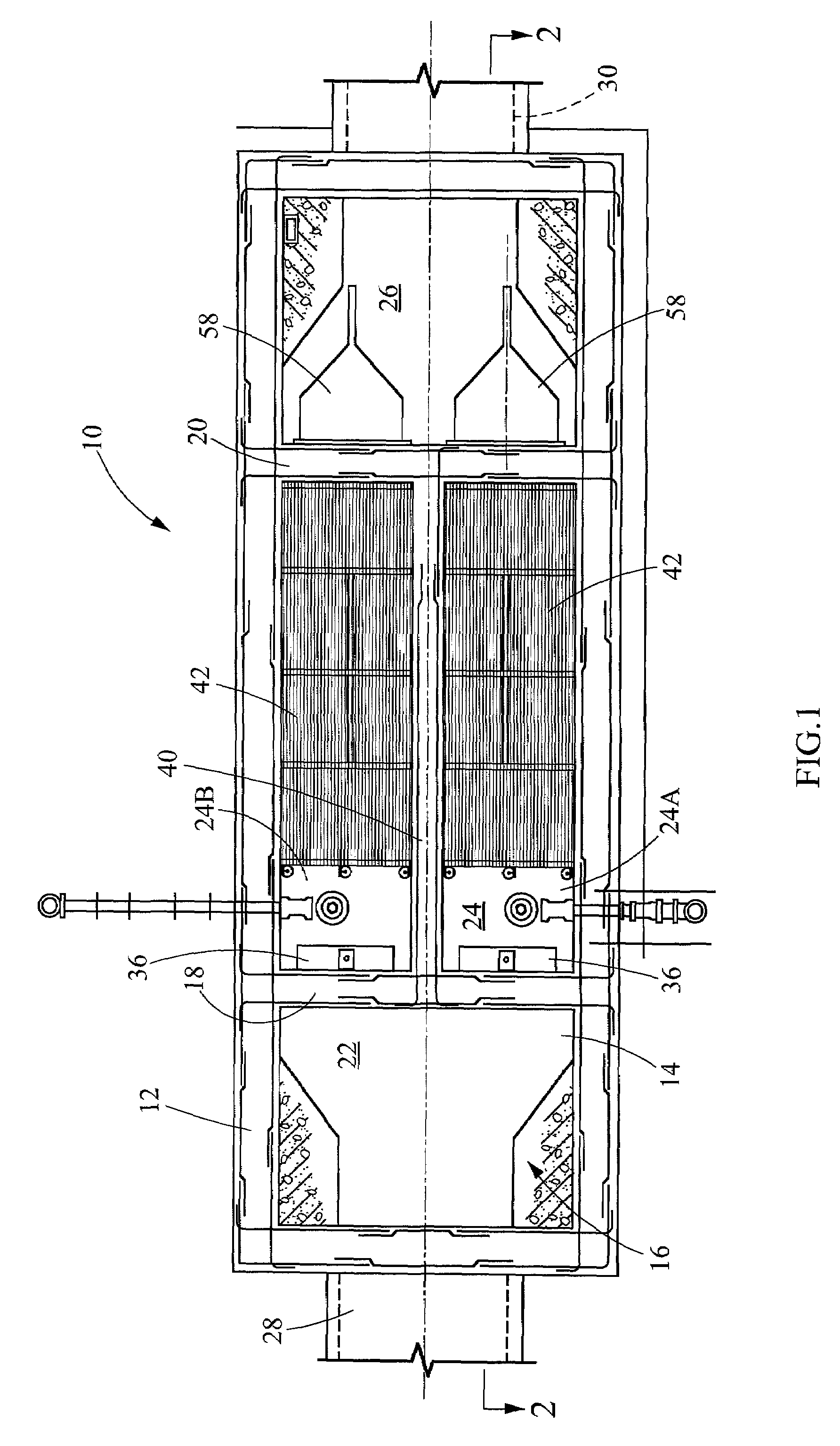
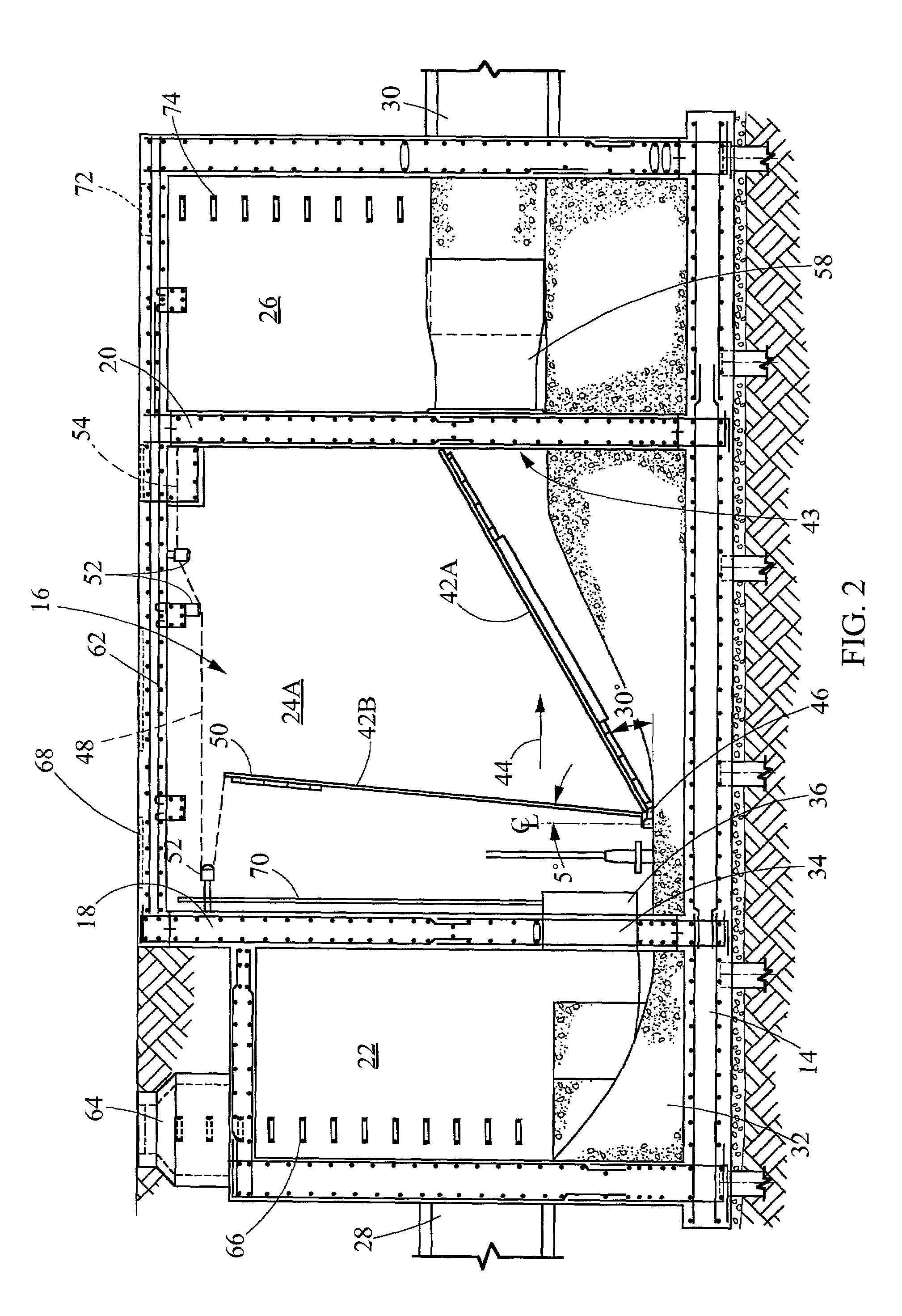
[0017]An apparatus for removing solid and floatable particulates from a wastewater stream is shown in a plan view with the cover removed in FIG. 1. The apparatus consists of a sidewall 12 and bottom wall 14 defining a chamber 16. The chamber 16 is divided by a first transverse partition 18 and a second transverse partition 20 into an inlet vessel 22, a screening vessel 24 and an outlet vessel 26. The chamber 16 also includes a wastewater inlet 28 and a wastewater outlet 30. Referring to FIG. 2, a concrete fillet 32 lies between the wastewater inlet 28 and the bottom wall 14. With continued reference to FIG. 2, the first partition 18 has an opening 34 between a bottom of the first partition 18 and the bottom wall 14. A sluice gate with anon-rising stem 36 is operatively associated with the opening 34 to selectively open and occlude the opening. In some applications a sluice grating with a rising stem may be preferred.

[0018]In a preferred embodiment, a lengthwise wall 40 divides the s...


PUM

PropertyMeasurementUnit
Angleaaaaaaaaaa
Angleaaaaaaaaaa
Angleaaaaaaaaaa

Abstract

An apparatus for removing particulates from a wastewater stream includes a chamber having a wastewater inlet and wastewater outlet which promotes a generally horizontal wastewater flow. A grating is provided in the chamber between the wastewater inlet and the wastewater outlet having a screen size for preventing the passage of particulates having greater than the select effective diameter from the wastewater inlet into the wastewater outlet. The grating is vertically inclined relative to the direction of the wastewater flow. A baffle within the chamber is configured to cooperate with the grating to generate a vortex in the wastewater having a velocity component parallel to the face of the grating which urges particles trapped by the grating along the grating toward a surface of the wastewater to suspend particles in the wastewater as the wastewater flows between the wastewater inlet and the wastewater outlet.

Description

TECHNICAL FIELD[0001]The present invention is directed to wastewater treatment, and more particularly to an apparatus and method for the removal of solids and floatables entrained within a wastewater flow.BACKGROUND ART[0002]In many parts of the United States, wastewater run-off from storm events is allowed to flow into natural waterways. However, particularly in urban areas, this wastewater is likely to entrain relatively innocuous particulate materials, such as sand, gravel and potentially more objectionable particulates such as hypodermic needles and all manner of garbage. This can result in the discharge of highly undesirable debris into natural waterways.[0003]The problem described above is exasperated in those areas having combined wastewater and sewage conveying systems. As used herein “wastewater” shall mean either storm run-off or combined sewage and storm run-off. Combined conveying systems are particularly common in the eastern half of the United States. During times of m...

Claims


Application Information

Patent Timeline
IPC IPC(8): E03F5/14
CPCE03F5/14
Inventor O'CONNOR, KELLYVAN DER TAK, LAURENSWOLLMANN, ALBERT M.
Owner CH2M HILL
Learn More