Filter design algorithm for multi-variate optical computing

Active Publication Date: 2006-11-21
HALLIBURTON ENERGY SERVICES INC
View PDF38 Cites 137 Cited by
  • Summary
  • Abstract
  • Description
  • Claims
  • Application Information

AI Technical Summary

Problems solved by technology

That is, it is impossible under the assumed condit

Method used


Image

  • Filter design algorithm for multi-variate optical computing
  • Filter design algorithm for multi-variate optical computing
  • Filter design algorithm for multi-variate optical computing

Examples


Embodiment Construction

[0029]Reference will now be made in detail to presently preferred embodiments of the invention, one or more examples of which are illustrated in the accompanying drawings. Each example is provided by way of explanation of the invention, not limitation of the invention. In fact, it will be apparent to those skilled in the art that modifications and variations can be made in the present invention without departing from the scope or spirit thereof. For instance, features illustrated or described as part of one embodiment may be used on another embodiment to yield a still further embodiment. Thus, it is intended that the present invention covers such modifications and variations as come within the scope of the appended claims and their equivalents.

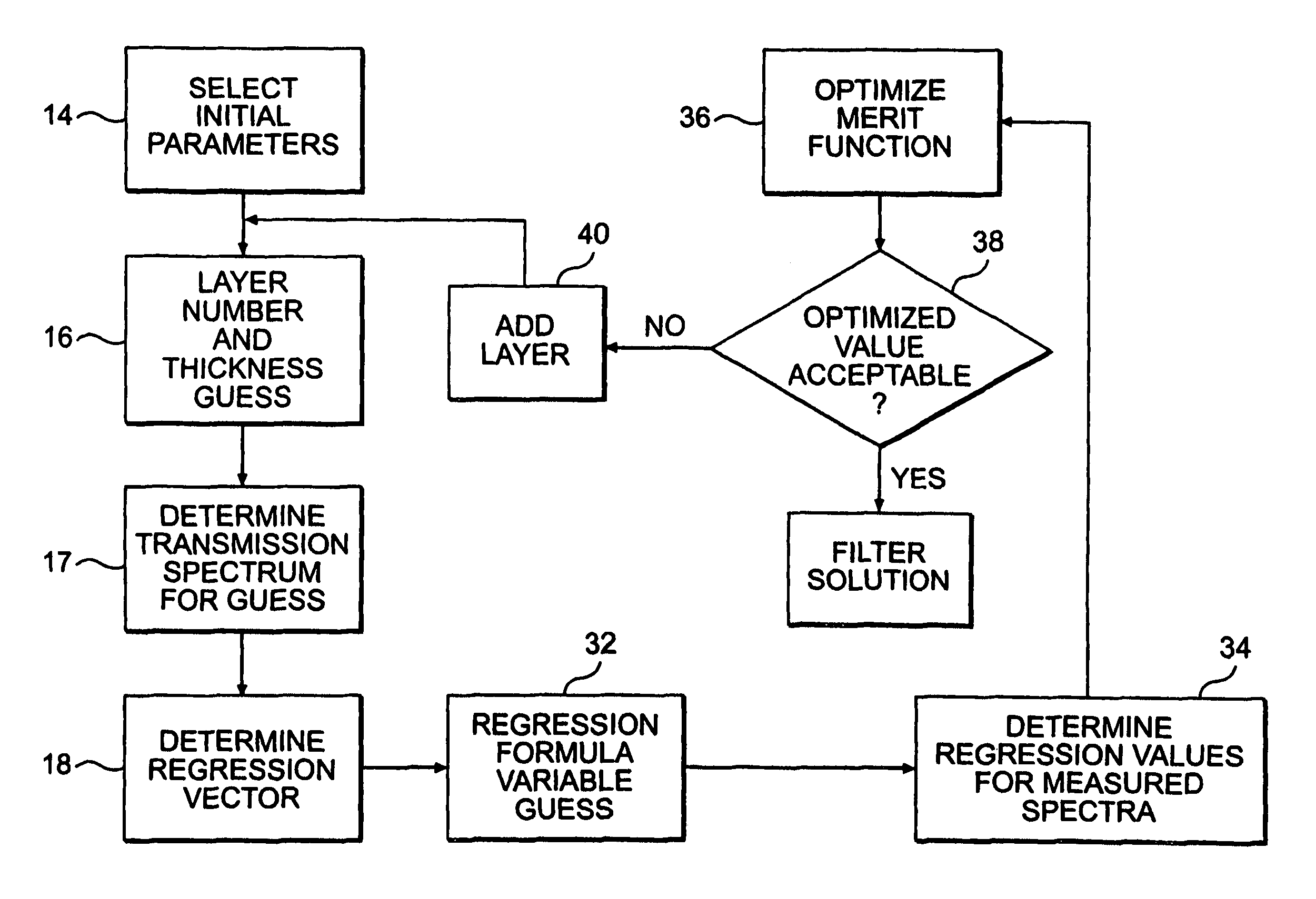
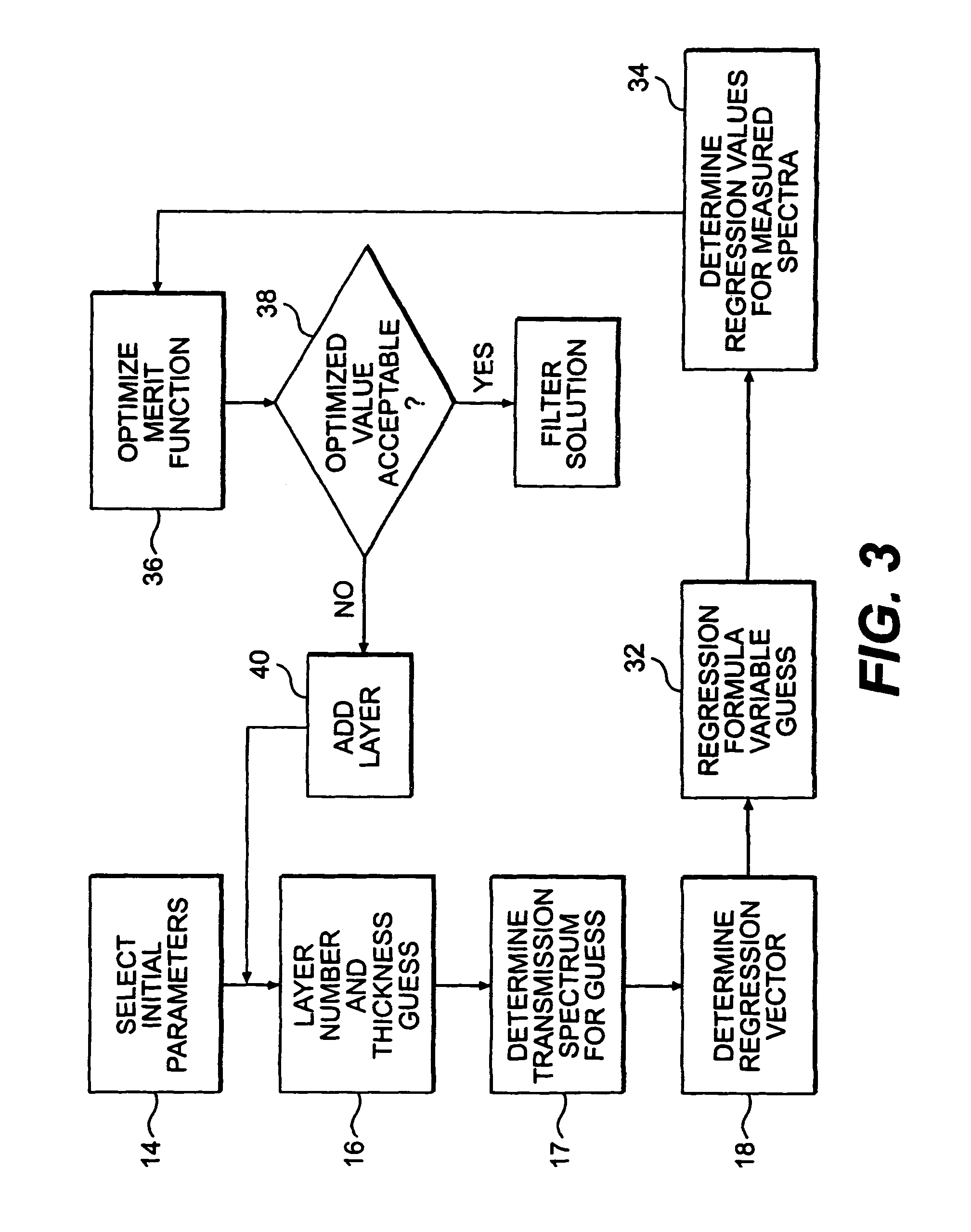
[0030]In one embodiment of the present invention, optical filter design parameters are optimized to conform to sample spectroscopic measurements, as opposed solely to a predetermined regression vector. As described in the '531 patent, a regres...


PUM

PropertyMeasurementUnit
Thicknessaaaaaaaaaa
Transmissionaaaaaaaaaa
Transmission spectrumaaaaaaaaaa

Abstract

Within a method of making an optical interference filter, sample spectra and measurements of a predetermined characteristic associated with respective spectra are provided. Upon selection of an initial number of filter layers and a thickness for each layer, a transmission spectrum is determined. Each sample spectrum is applied to a regression formula that relates interaction of light with the transmission spectrum to a regression value. A comparison relationship between the calculated regression values and the sample measurements is defined and optimized, wherein thickness of each layer is an optimization variable.

Description

[0001]This application claims priority to U.S. Provisional Application No. 60 / 235,336 filed Sep. 26, 2000, the entire disclosure of which is incorporated herein by reference.[0002]The U.S. Government has a paid-up license in this invention and the right in limited circumstances to require the patent owner to license others on reasonable terms as provided for by the terms of Grant No. N00014-97-1-0806 awarded by the Office of Naval Research and Grant No. F33615-00-2-6059 awarded by the Air Force Research Laboratory.BACKGROUND OF THE INVENTION[0003]The present invention relates to the design of optical filters for use in spectroscopy analysis systems.[0004]As described in U.S. Pat. No. 6,198,531, the entire disclosure of which is incorporated by reference herein, methods are known by which to construct optical filters having predetermined transmission spectra. In general, such an optical filter is an interference filter having alternating layers of high and low refractive index materi...

Claims


Application Information

Patent Timeline
IPC IPC(8): C23C16/52C23C14/54
CPCG02B5/285G02B27/0012
Inventor MYRICK, MICHAEL L.SOYEMI, OLUSOLA O.GEMPERLINE, PAUL J.
Owner HALLIBURTON ENERGY SERVICES INC
Why Eureka
Try Eureka