Microprocessor integrated multifunction hoist system controller

a multi-function, microprocessor technology, applied in the direction of hoisting equipment, instruments, analogue processes for specific applications, etc., can solve the problems of cable failure, high cost, and sometimes disastrous effects, and damage to the rig or hoisting equipmen

Active Publication Date: 2006-11-21
NIELD BARRY J
View PDF10 Cites 27 Cited by
  • Summary
  • Abstract
  • Description
  • Claims
  • Application Information

AI Technical Summary

Problems solved by technology

These rigs can experience certain conditions that result in the main hoist block of the hoist system traveling into too close proximity of the cable support mechanism at the top of the rig supporting the hoist block and equipment and personnel on the rig's deck.
The load block exceeding the upper and lower travel limits can result in damage to the rig or hoist equipment and possible injury to the operating personnel.
Movement of such high masses can create an extreme condition of momentum that can cause a travel block to exceed a set-distance type travel limit that it otherwise would not—especially a lower limit.
Exceeding the albeit theoretical ton-mile capacity of a cable can result in failure of the cable with expensive and sometime disastrous results.
Also to be avoided is the allowance of too large a safety margin (e.g., caused by an inability to accurately determine the ton-mile wear on a cable), resulting in lost time and added expense when unnecessarily replacing a cable that still has substantial useful life.

Method used


Image

  • Microprocessor integrated multifunction hoist system controller
  • Microprocessor integrated multifunction hoist system controller
  • Microprocessor integrated multifunction hoist system controller

Examples


Embodiment Construction

[0021]Referring now to the drawings, the details of preferred embodiments of the present invention are graphically and schematically illustrated. Like elements in the drawings are represented by like numbers, and any similar elements are represented by like numbers with a different lower case letter suffix.

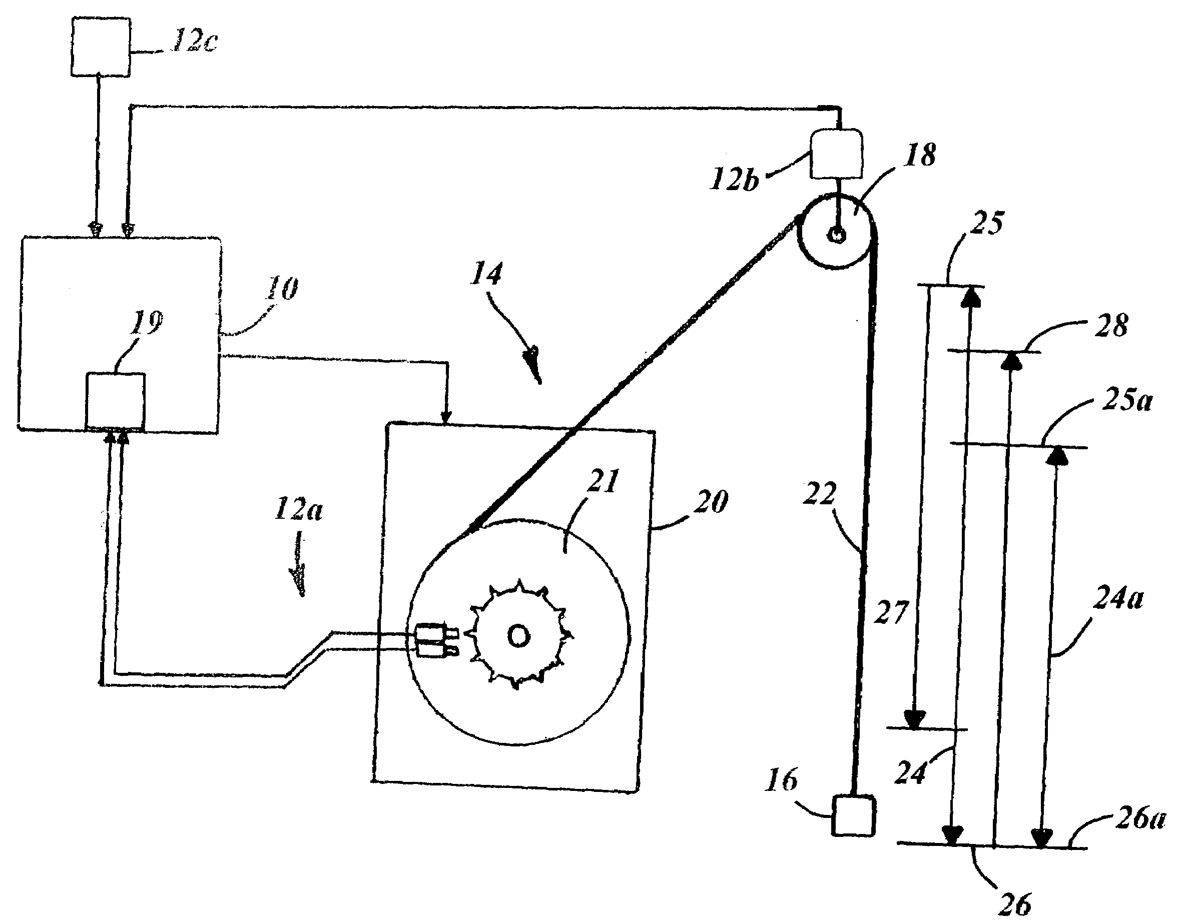
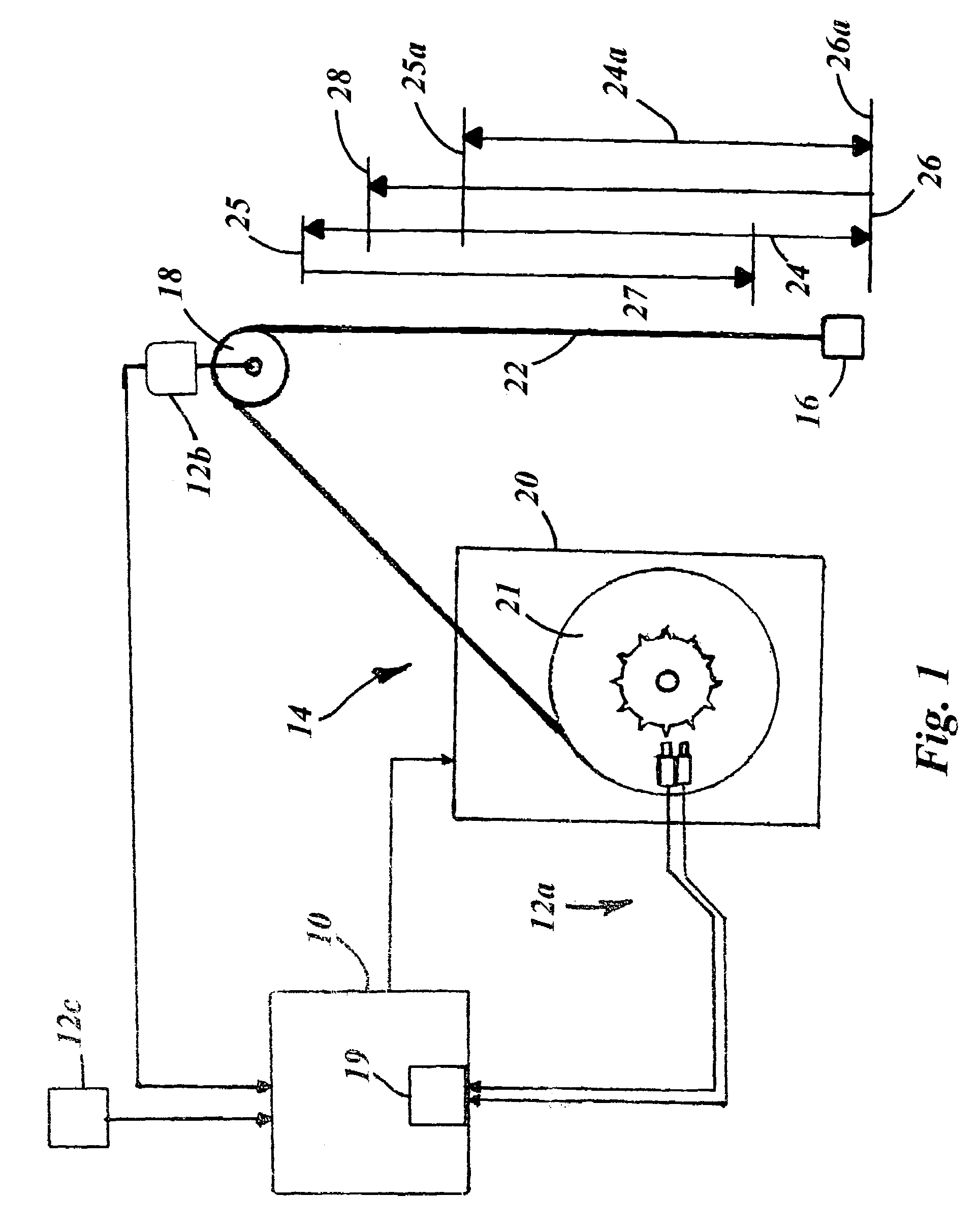
[0022]The present invention, an embodiment of which is illustrated in FIG. 1, is a multi-function cable hoist system controller 10. The present cable hoist system 10 is intended for use in combination with a heavy hoist system 14 such as is used in the petroleum production industry on drilling and servicing rigs. As disclosed herein, the present hoist system controller 10 can accomplish a plurality of functions relating to limiting the (ravel of the hoist block 16 of a heavy cable hoist system 14. These travel limit functions include monitoring the speed of the traveling block 16, as well as limiting the travel range of the block 16 to avoid its approach too close to the stationar...


PUM


Abstract

The present multi-function cable hoist system controller monitors a variety of drilling rig hoist system functions, including: positioning of the hoist block of the hoist system, speed / momentum of the hoist block, and hoist block loading. The controller can also monitor: cable ton-mile parameters, weight on the drill bit, and drill bit penetration rate. The controller automatically controls operation of the hoist system's drawworks when the system's operation exceeds certain preset and user specified parameters. The controller has a housing containing a microprocessor, supporting circuitry, and input and output systems. An instruction set digitally stored on the microprocessor codes for the functional features of the controller and enables it to process inputs and to generate outputs to accomplish the controller's functions. Device input means and display / alarm means are mounted on the front panel of the housing. A drawworks output communicates drawworks control signals to the hoist system.

Description

[0001]The present application claims the benefit of prior filed U.S. Provisional Application, Ser. No. 60 / 557,409 filed 29 Mar. 2004, to which the present application is a US national utility patent application.FIELD OF THE INVENTION[0002]The present invention is in the field of electrical computer based communications. More specifically, the present invention relates to microprocessor controlled circuits and signals responsive to the proximity or distance of an object coming too close to or moving too far from another object, and is useful for setting, controlling and displaying travel limits and ton-mile data of hoist equipment used on cranes, general hoists and drill rigs.BACKGROUND OF THE INVENTION[0003]In the oil production industry, hoist systems are used for drilling and other operations associated with drilling rigs and well service rigs. These rigs can experience certain conditions that result in the main hoist block of the hoist system traveling into too close proximity of...

Claims


Application Information

Patent Timeline
Patent Type & Authority Patents(United States)
IPC IPC(8): G08B21/00B66D1/40B66D1/54E21B44/02G06F7/00
CPCB66D1/40B66D1/54E21B44/02
Inventor NIELD, BARRY J.
Owner NIELD BARRY J
Why Eureka
Try Eureka