

Reflector antenna radome with backlobe suppressor ring and method of manufacturing
a technology of suppressor rings and reflector antennas, which is applied in the direction of collapsible/retractable loop antennas, antenna details, antennas, etc., can solve the problems of increasing overall antenna and antenna support structure costs, reducing overall antenna efficiency, and overall siz
- Summary
- Abstract
- Description
- Claims
- Application Information
AI Technical Summary
Benefits of technology
Problems solved by technology
Method used
Image

Examples
Embodiment Construction
[0015]The invention is described in an exemplary embodiment applied upon a radome also having toolless quick attach / detach features further described in U.S. utility patent application Ser. No. 10 / 604,756 “Dual Radius Twist Lock Radome and Reflector Antenna for Radome”, by Junaid Syed et al, filed Aug. 14, 2003 and hereby incorporated by reference in the entirety. The invention is described herein with respect to a single profile radome. One skilled in the art will appreciate that the invention may also be applied, for example, to the dual radius radome configurations disclosed in the aforementioned application.
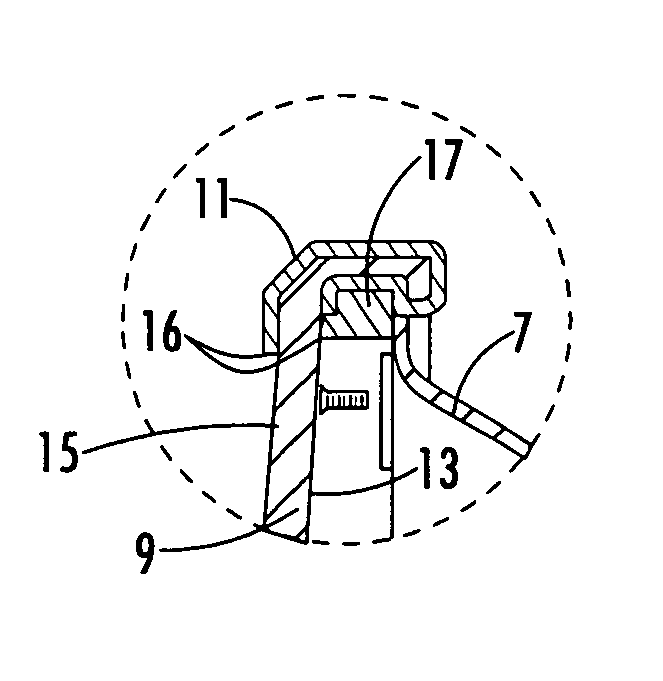
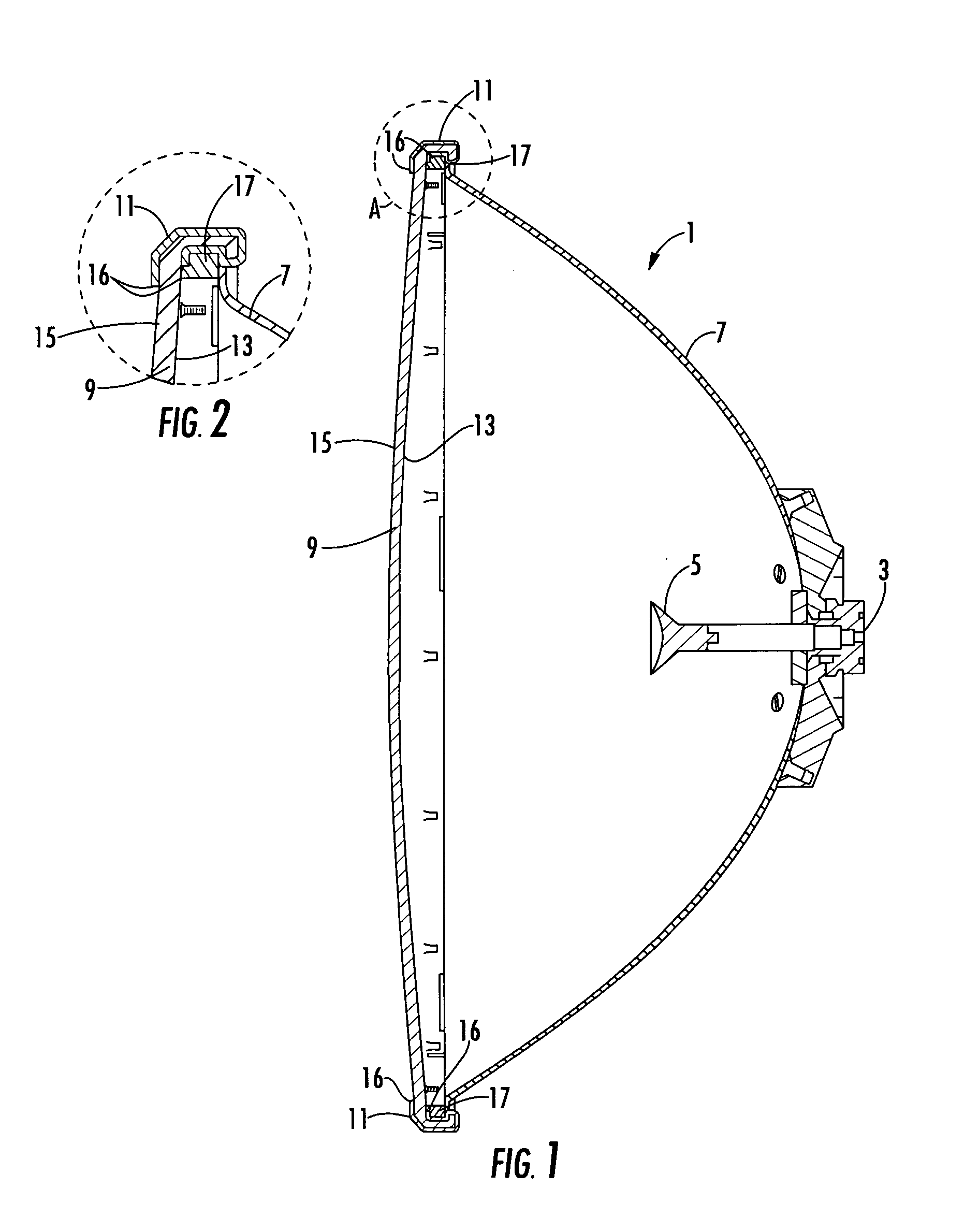
[0016]As shown in FIG. 1, a typical deep dish reflector antenna 1 projects a signal from a feed 3 upon a sub reflector 5 which reflects the signal to illuminate the reflector 7. A radome 9 covers the open distal end of the reflector 7 to form an environmental seal and reduce the overall wind load of the antenna 1.
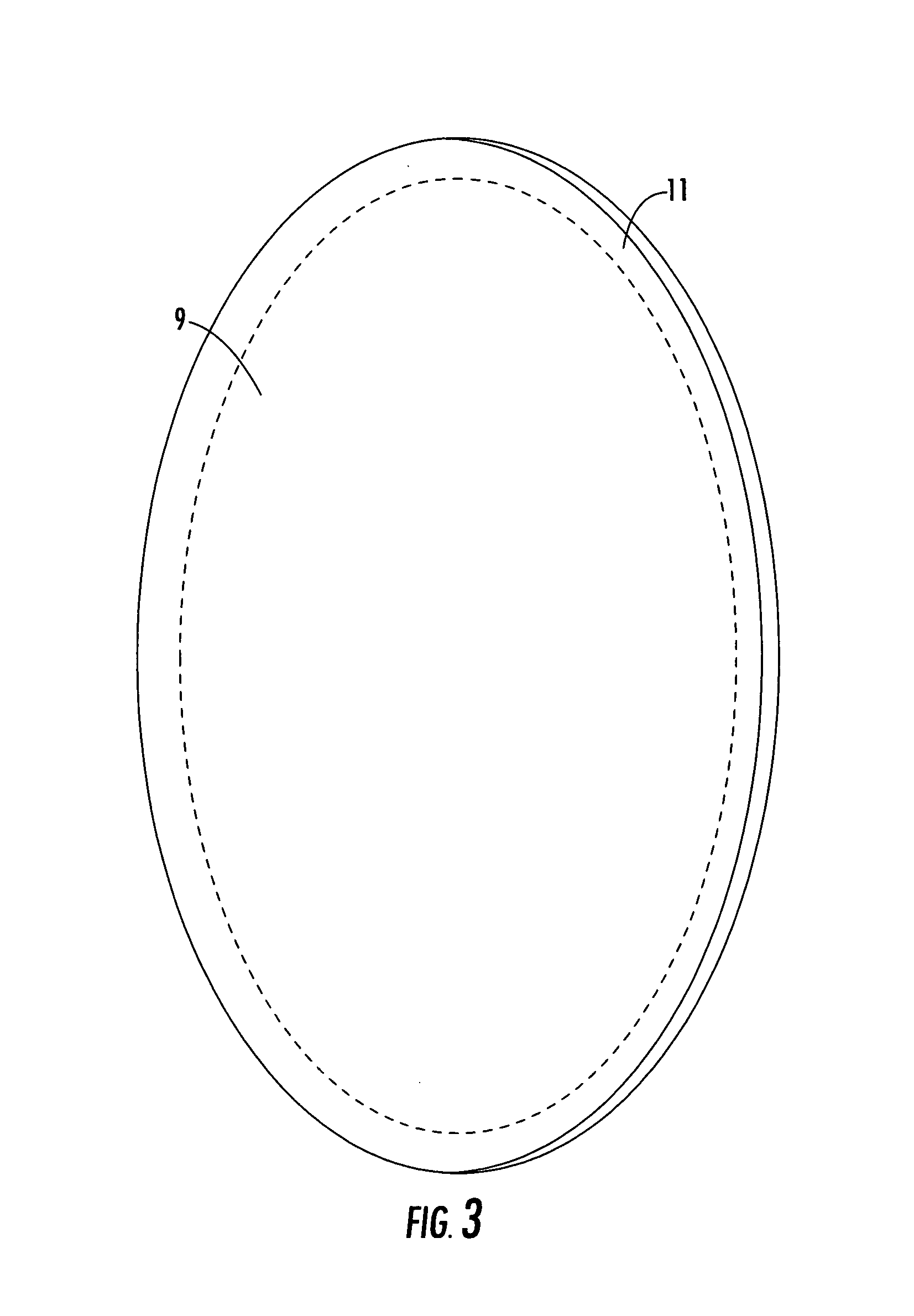
[0017]As shown in FIGS. 2 and 3, a conductive ring herein after...
PUM
 Abstract
Description
Claims
Application Information