Image synthesis display method and apparatus for vehicle camera

Active Publication Date: 2006-11-21
PANASONIC CORP
View PDF20 Cites 85 Cited by
  • Summary
  • Abstract
  • Description
  • Claims
  • Application Information

AI Technical Summary

Benefits of technology

[0012]It is, therefore, one objective of the present invention to provide an image synthesis and display method for a vehicle camera, whereby an

Problems solved by technology

When an automobile is being driven backward, it is difficult for the driver to obtain an unobstructed view to the rear, and the angle of vision produces a blind spot.
However, when images obtained by multiple monitoring cameras mounted on a vehicle are merely synthesized, the resulting synthesized image tends not to be easily seen on the screen of a display device.
However, when images obtained by multiple vehicle cameras are synthesized, as is described above, as time elapses the luminance and t

Method used


Image

  • Image synthesis display method and apparatus for vehicle camera
  • Image synthesis display method and apparatus for vehicle camera
  • Image synthesis display method and apparatus for vehicle camera

Examples


Example

[0035]One embodiment of the present invention will now be described while referring to the drawings.

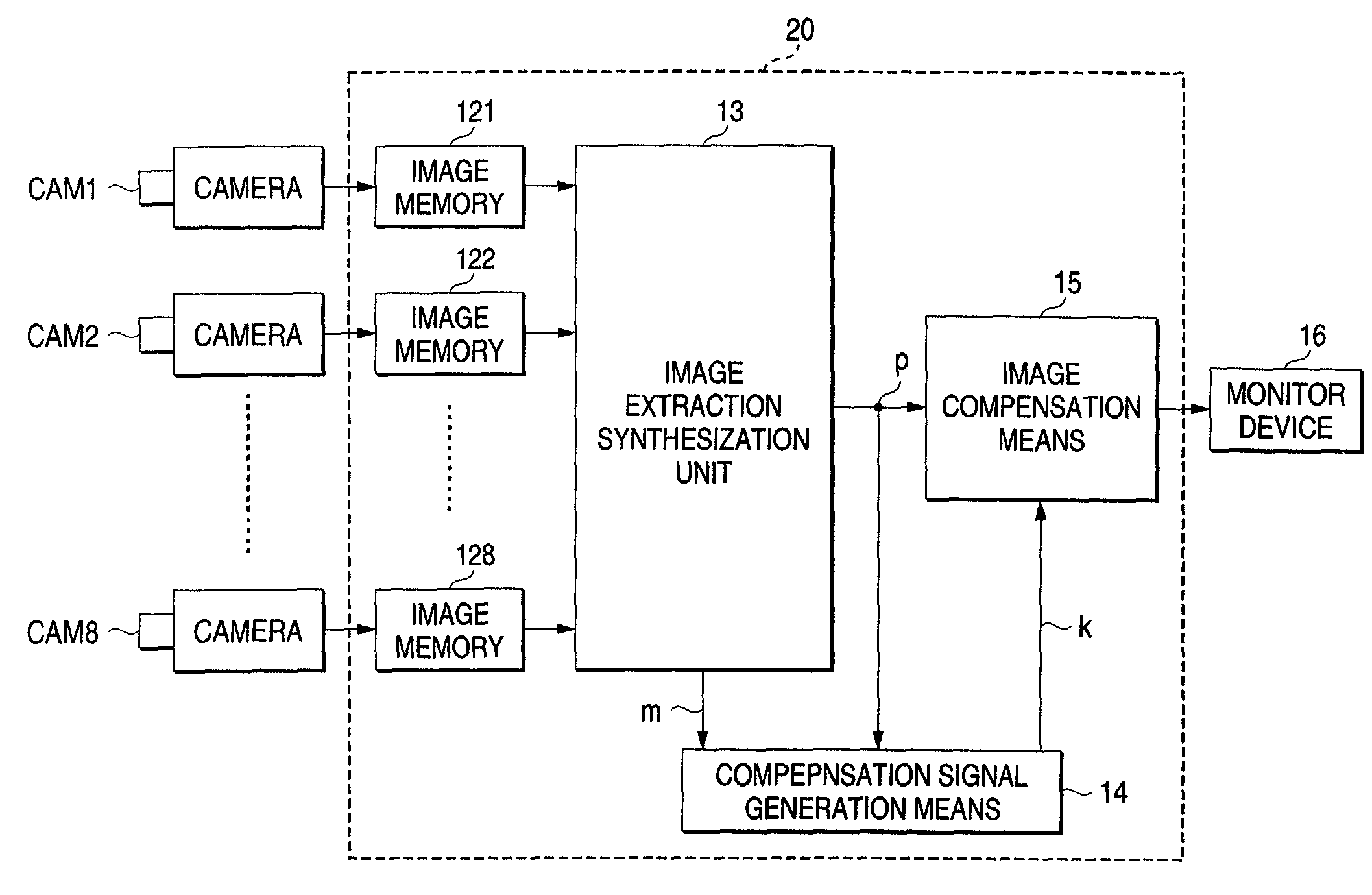
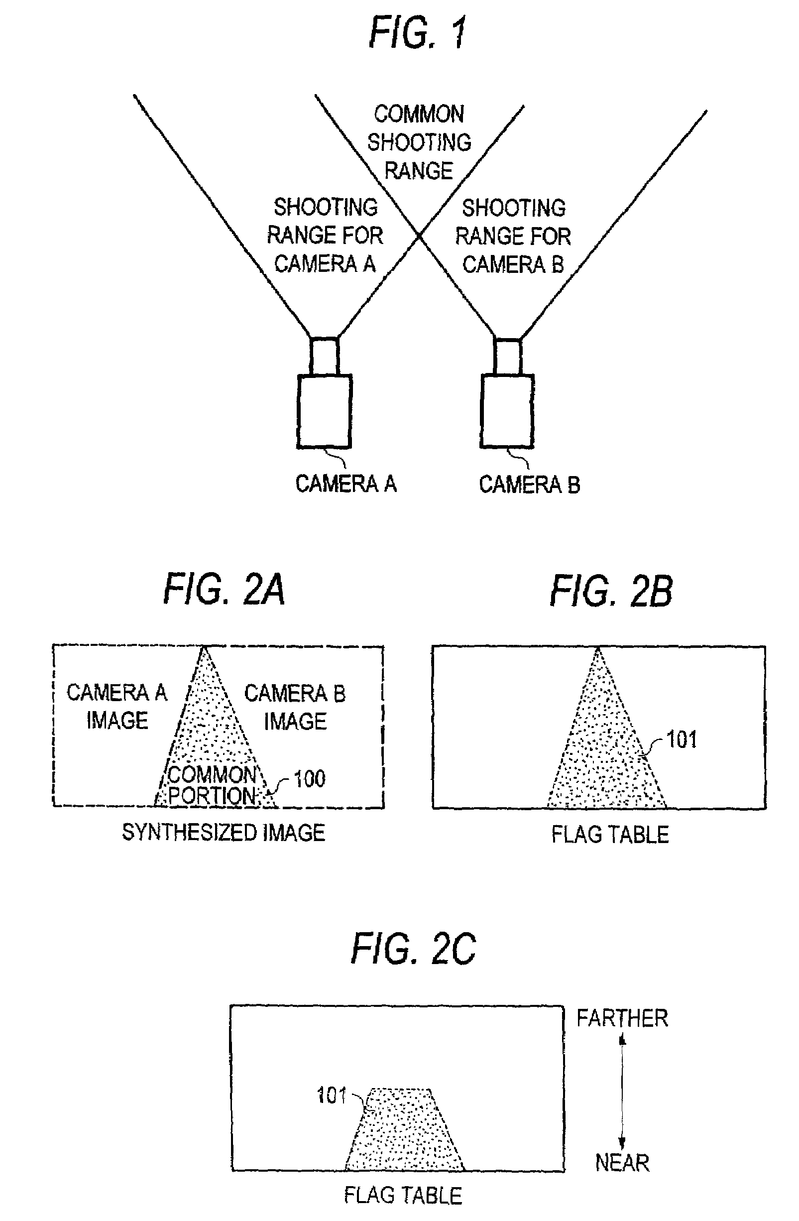
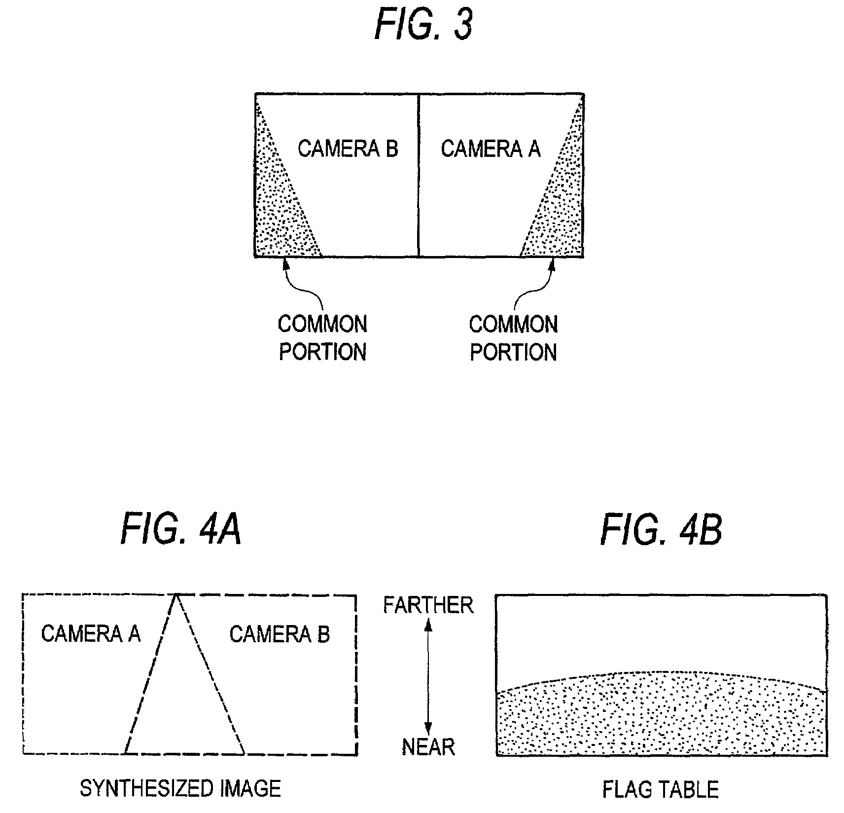
[0036]FIG. 1 is a diagram showing an example of the shooting ranges for two vehicle cameras. Two adjacent vehicle cameras A and B are fixedly arranged so that their shooting ranges slightly overlap. Manufacturing variances are present even among multiple vehicle cameras of the same model that are mounted on a vehicle, and the luminance and the image color balance obtained by each camera differ because each camera individually controls the ALC (auto iris control), the ELC (auto shutter control), the AGC (auto gain control) and the ATW (auto white balance). Furthermore, as previously described, since one camera could be facing the sun while another is fully shaded from the sun, when images obtained by such cameras are merely synthesized, the differences between the original images would be too great to yield an acceptable synthesized image, and it would not be easy for a driver to view ...


PUM


Abstract

When multiple cameras (CAM1) to (CAM8) for shooting the periphery of a local vehicle are mounted on the vehicle, and when obtained camera images are to be synthesized to display a synthesized image on the screen of a display device (16), the pixel data for the camera images constituting the synthesized image are compensated for, so that differences in the pixel data for adjacent camera images is reduced. For example, the pixel data are corrected so their values equal the average values of the pixel data for the adjacent camera images. Therefore, an easily viewed image, produced by synthesizing the images obtained by the multiple vehicle cameras, can be displayed on the monitor device (16).

Description

BACKGROUND OF THE INVENTION[0001]1. Technical Field of the Invention[0002]The present invention relates to an image synthesis display method, and an apparatus therefor, for synthesizing images obtained by multiple vehicular mounted cameras and for displaying the synthesized images. In particular, the present invention relates to an image synthesis display method and apparatus for a vehicle camera for generating in real time a synthesized image that can easily be viewed on a display screen.[0003]2. Description of the Related Art[0004]When an automobile is being driven backward, it is difficult for the driver to obtain an unobstructed view to the rear, and the angle of vision produces a blind spot. Further, even while a vehicle is moving forward, when another vehicle travelling a parallel course reaches a position whereat it is obscured by a door pillar, that vehicle disappears from the driver's sight. Recently, therefore, vehicular mounted cameras have been used to monitor peripheral...

Claims


Application Information

Patent Timeline
IPC IPC(8): G06K9/00B60Q1/00G06K9/18H04N7/18B60R21/00B60R1/00G06T1/00G06T3/00G06T5/00G06T5/50G06T7/00G06V30/224H04N5/265
CPCB60R1/00G06T3/4038G06T7/0024H04N7/181B60R2300/105B60R2300/303B60R2300/607G06T2207/30252G06T7/30
Inventor KATO, KOICHISUZUKI, MAKOTOFUJITA, YUKIOHIRAMA, YUICHI
Owner PANASONIC CORP
Why Eureka
Try Eureka