
Apparatus detecting abnormality of exhaust system of internal combustion engine

an internal combustion engine and abnormality detection technology, applied in the direction of exhaust treatment electric control, electrical control, instruments, etc., can solve the problems of poor detection precision, reduced decision-making precision, and unsatisfactory control of the internal combustion engine's each system, and achieve high precision

Inactive Publication Date: 2006-11-21
TOYOTA JIDOSHA KK
View PDF12 Cites 8 Cited by
  • Summary
  • Abstract
  • Description
  • Claims
  • Application Information

AI Technical Summary

Benefits of technology

The present invention provides an apparatus for detecting abnormalities in an internal combustion engine's exhaust system with high precision. The apparatus includes two air fuel ratio detectors placed close to the engine, an air intake sensor, and a detector that uses the difference between the two air fuel ratio detectors to detect abnormalities in the exhaust system. The apparatus can accurately detect leaks in the exhaust system and can also detect changes in air fuel ratio caused by the leak. This allows for timely maintenance and repair of the engine.

Problems solved by technology

If the exhaust system or the like has trouble, however, the internal combustion engine's each system is unsatisfactorily controlled.
If a decision that exhaust gas is leaking is made from a modified value for a single condition of operation exceeding a prescribed value, a base air fuel ratio with an offset associated with variation in production, degradation with time and the like contributes to reduced precision for decision.
However, the apparatus disclosed in Japanese Patent Laying-Open No. 10-47130, comparing a learning feedback value and a set feedback value to detect abnormality, provides poor precision for detection and also consumes time for detection.
This is because the feedback control employs a learning value used to eliminate effects of a variety of variations to determine abnormality and it is difficult to separate the variations and the occurrence of abnormality.
As such, improved precision for determination of abnormality can hardly be achieved and to provide such an improved precision a severer condition for detection of abnormality is unavoidable.
This results in limited occasion for detection of abnormality and if abnormality occurs it may not be detected.
In this regard, the apparatus can have a disadvantage similar to that of Japanese Patent Laying-Open No. 10-47130.

Method used


Image

  • Apparatus detecting abnormality of exhaust system of internal combustion engine
  • Apparatus detecting abnormality of exhaust system of internal combustion engine
  • Apparatus detecting abnormality of exhaust system of internal combustion engine

Examples


first embodiment

[0045

[0046]The present invention in a first embodiment provides an abnormality detection system, as will be described hereinafter.

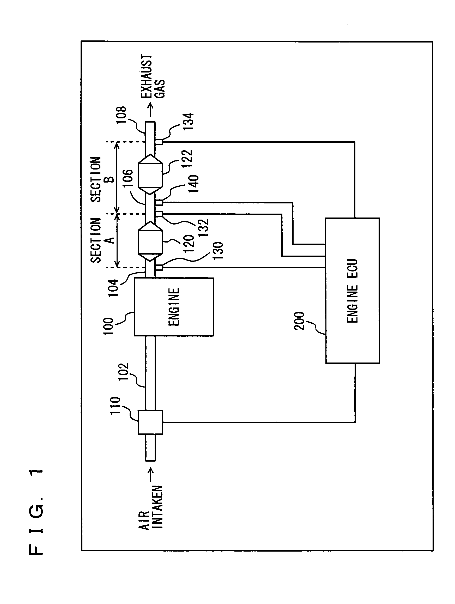
[0047]FIG. 1 is a general, control block diagram of the abnormality detection system. As shown in FIG. 1, the abnormality detection system detects abnormality occurring in an internal combustion engine 110 at exhaust pipes 104, 106, 108. The abnormality detection system includes: engine 100; an air intake pipe 102 sending air into engine 100; exhaust pipe 104, 106, 108 exhausting gas from engine 100; an airflowmeter 110 arranged at air intake pipe 102, a first catalyst 120 arranged between exhaust pipes 104 and 106; a second catalyst 122 arranged between exhaust gas 106 and exhaust pipe 108; an air fuel ratio sensor 130 arranged upstream of the first catalyst 120 (or closer to engine 100); a second air fuel ratio sensor 132 arranged between the first and second catalysts 120 and 122; a third air fuel ratio sensor 134 arranged downstream of the second cata...

second embodiment

[0083

[0084]The present invention in a second embodiment provides an abnormality detection system as will be described hereinafter. Note that the present embodiment's abnormality detection system has the same hardware configuration as that of the abnormality detection system described in the first embodiment (as shown in FIG. 1).

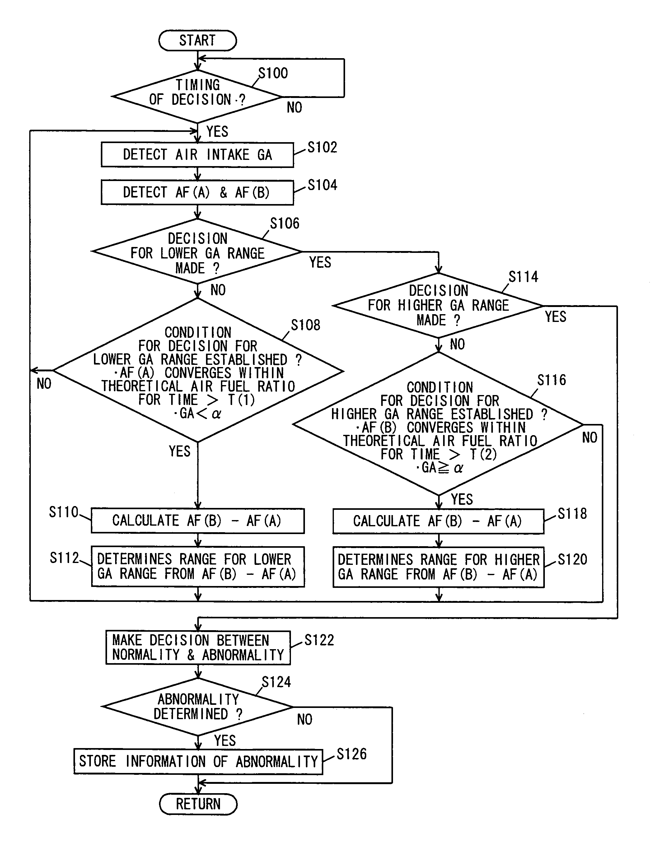
[0085]Reference will now be made to FIG. 7 to describe a table stored in an engine ECU 200 of the abnormality detection system of the present embodiment. As shown in FIG. 7, the present embodiment provides engine ECU 200 detecting normality / abnormality of the first, second and third air fuel ratio sensors 130, 132, 134 arranged at an exhaust pipe. Accordingly a decision is made on a relationship in magnitude between an absolute value of a difference between air fuel ratios detected by the three air fuel ratio sensors and predetermined threshold values β, γ, σ.

[0086]As indicated in FIG. 7, the first, second and third air fuel ratio sensors 130, 132 and 134 det...


PUM


Abstract

An engine ECU executes a program including the steps of: detecting an air intake; subtracting an air fuel ratio detected by an upstream air fuel ratio sensor from that detected by a downstream air fuel ratio sensor; using the calculated air fuel ratio difference to determine a range for a lower GA range; determining a range for a higher GA range; and determining from the combination of the determined ranges of the lower and higher GA ranges whether a section A's exhaust system operates normally or has abnormality.

Description

[0001]This nonprovisional application is based on Japanese Patent Application No. 2003-379935 filed with the Japan Patent Office on Nov. 10, 2003, the entire contents of which are hereby incorporated by reference.BACKGROUND OF THE INVENTION[0002]1. Field of the Invention[0003]The present invention relates generally to apparatuses detecting abnormality of internal combustions engines and particularly to those identifying abnormality of exhaust systems.[0004]2. Description of the Background Art[0005]For a vehicle's internal combustion engine an air intake system intakes air which is in turn mixed with a fuel provided from a fuel system and the air fuel mixture is combusted in a combustion chamber and an exhaust system exhausts gas. Accordingly the internal combustion engine's operation is controlled as based on detection signals issued from the air intake, fuel and exhaust systems, respectively.[0006]For such an internal combustion engine the exhaust system is provided with an exhaust...

Claims


Application Information

Patent Timeline
Patent Type & Authority Patents(United States)
IPC IPC(8): G01M15/05F02D45/00F01N3/18F01N11/00F02D41/14G06G7/70
CPCF01N11/007F02D41/1441F02D41/1495F01N2560/025F01N2560/14F02D41/187Y02T10/47Y02T10/40
Inventor SATOYA, KOICHI
Owner TOYOTA JIDOSHA KK
Learn More