Brake

a technology of brakes and cylinders, applied in the field of motors, can solve the problem of supplemental braking force being applied to the motor drive sha

Inactive Publication Date: 2006-11-28
AUTOADAPT
View PDF14 Cites 16 Cited by
  • Summary
  • Abstract
  • Description
  • Claims
  • Application Information

AI Technical Summary

Benefits of technology

[0010]Rotation of a drive shaft or similar component during motor operation disengages one or more brake pads from frictional engagement with a stationary part of the motor or other stationary braking surface. When the motor is de-energized, slowing shaft rotation automatically brings one or more brake pads back into frictional engagement with the braking surface. Control of the brake pads' positioning is based on balancing the centrifugal force created by shaft rotation with a biasing centripetal force. Typically, only a supplemental braking force must be applied to the motor drive shaft due to a significant amount of internal friction against unwanted drive shaft rotation when the motor is not energized.

Problems solved by technology

Typically, only a supplemental braking force must be applied to the motor drive shaft due to a significant amount of internal friction against unwanted drive shaft rotation when the motor is not energized.

Method used


Image

  • Brake
  • Brake
  • Brake

Examples


Embodiment Construction

[0023]The following detailed description of the invention will refer to one or more embodiments of the invention, but is not limited to such embodiments. Rather, the detailed description is intended only to be illustrative. Those skilled in the art will readily appreciate that the detailed description given herein with respect to the Figures is provided for explanatory purposes as the invention extends beyond these limited illustrative and exemplary embodiments.

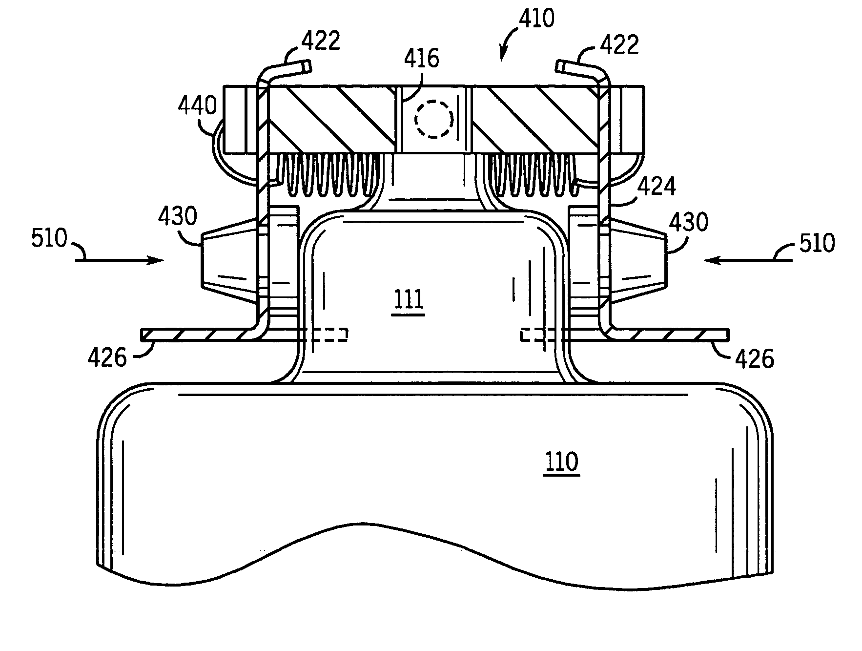
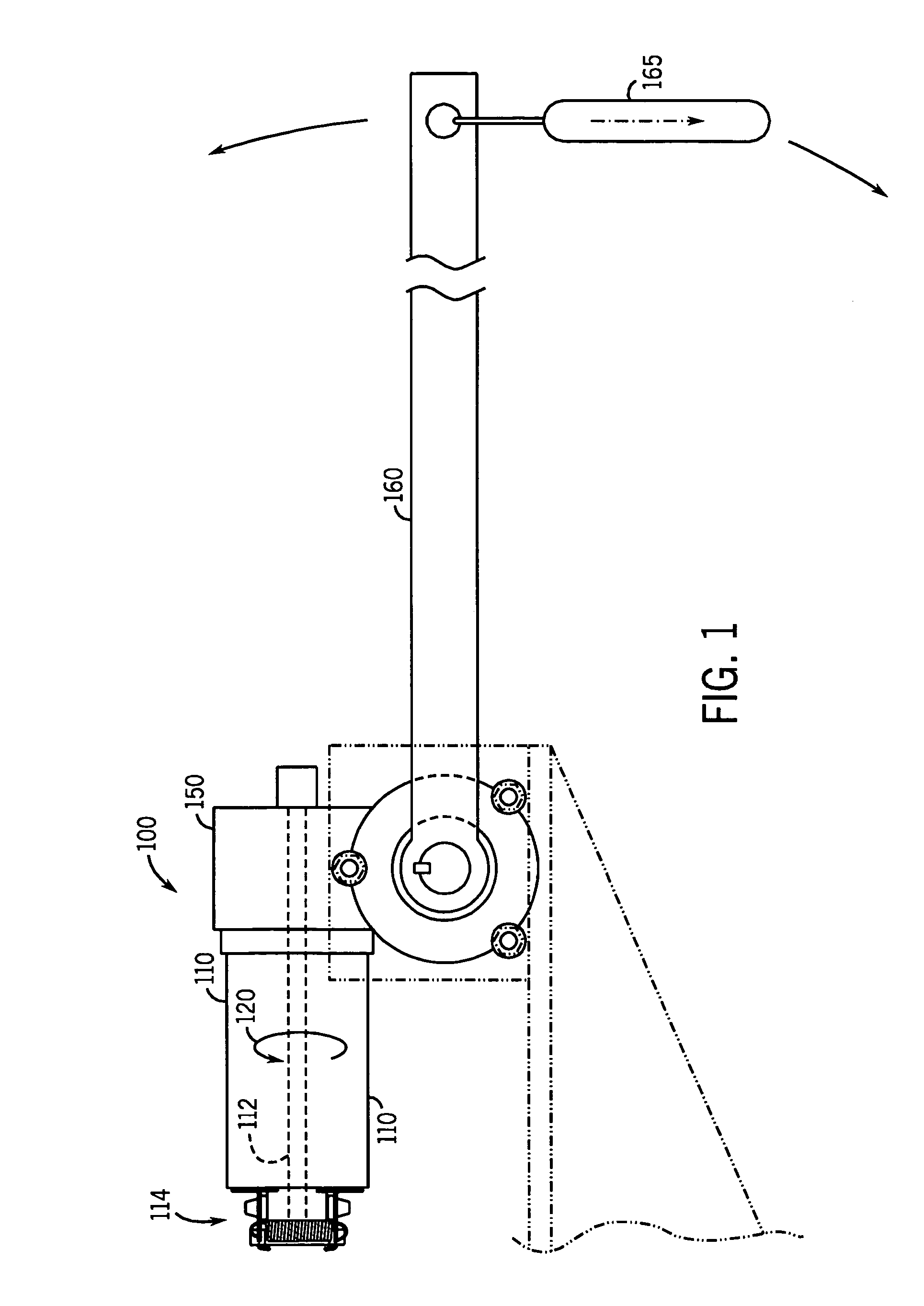
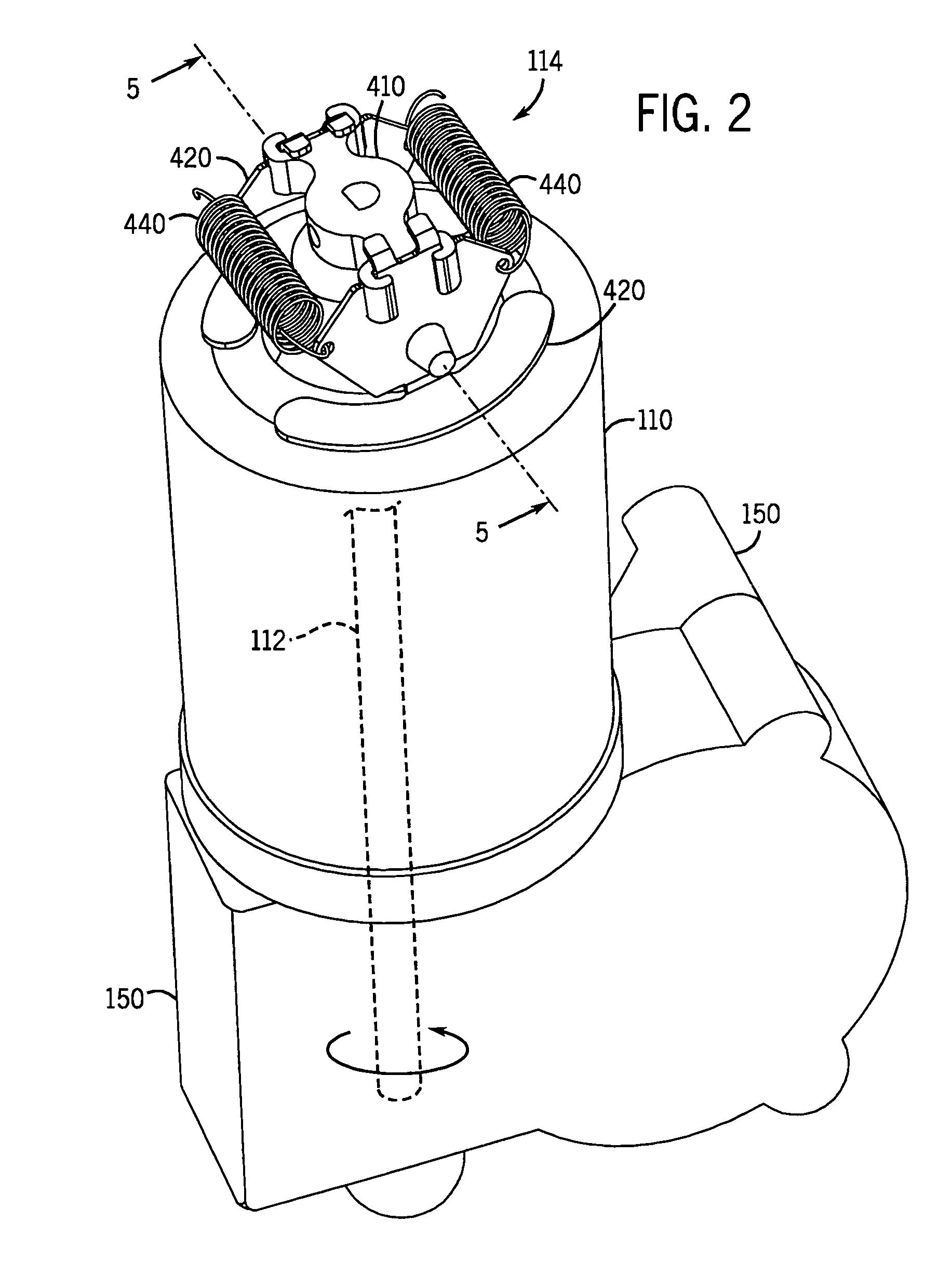
[0024]The present invention uses the rotation of a motor shaft or similar component during operation to disengage one or more brake pads from frictional engagement with a stationary part of the motor or other stationary braking surface or member. Likewise, the slowing rotation of the shaft after power to the motor is turned off automatically brings one or more brake pads into frictional engagement with the braking surface. This control of the brake pads is based on balancing the centrifugal force created by rotation of the mo...


PUM


Abstract

A motor brake can be coupled to the rotatable motor drive shaft. The brake includes a shaft-mountable support that rotates uniformly with the drive shaft. One or more brake shoes, which can include flyweights or the like, are hingedly mounted to the support and include brake pads. A centripetal force is applied to the brake shoes using one or more springs or other biasing means that bias the brake pads against a braking surface when rotation of the shaft is below a minimum rotational velocity. The brake pads disengage from the braking surface when shaft rotation exceeds the minimum rotational velocity. The centrifugal force induced and applied to the brake shoes and brake pads by rotation of the motor drive shaft overcomes the biasing force to disengage the brake pads from the braking surface, which may be the housing of a motor to which the brake is affixed.

Description

CROSS-REFERENCE TO RELATED APPLICATIONS[0001]Not applicable.STATEMENT REGARDING FEDERALLY SPONSORED RESEARCH OR DEVELOPMENT[0002]Not applicable.REFERENCE TO SEQUENCE LISTING, A TABLE, OR A COMPUTER PROGRAM LISTING COMPACT DISK APPENDIX[0003]Not applicable.BACKGROUND OF THE INVENTION[0004]1. Field of the Invention[0005]The present invention relates generally to motors employing rotating elements such as drive shafts. More specifically, the present invention relates to a braking system that can be used on a motor drive shaft and / or the like that is intended to remain stationary when the motor is not energized.[0006]2. Description of Related Art[0007]Many motors and other mechanisms employ drive shafts and the like as rotating elements or components. When a motor is energized (that is, turned on), the drive shaft rotates, transferring power to another component, such as a pulley, gear or gearbox. When the motor is turned off, the drive shaft should remain motionless. In many cases, for...

Claims


Application Information

Patent Timeline
Patent Type & Authority Patents(United States)
IPC IPC(8): A01H5/02F16D59/00
CPCF16D49/16F16D2127/002
Inventor APPELQVIST, ROGER L. E.
Owner AUTOADAPT
Why Eureka
Try Eureka