Slide latch

a latch and sliding technology, applied in the direction of fastening means, carpet fasteners, mechanical devices, etc., can solve the problems of springs being subject to breakage, prior art latches with integrally molded spring elements may not have the same life expectancy as those using separate metal springs

Inactive Publication Date: 2006-11-28
SOUTHCO
View PDF31 Cites 21 Cited by
  • Summary
  • Abstract
  • Description
  • Claims
  • Application Information

AI Technical Summary

Benefits of technology

[0015]The latch includes a generally flat, rectangular plate which is positioned above the door panel when the latch is mounted in the opening. In a presently preferred embodiment, the plate extends beyond the edge of the panel and over the top of the frame, thereby serving to prevent inward movement of the panel beneath the frame.
[0018]Preferably, the latch also includes camming means for controlling the travel of the actuator when the actuator is operated. The camming means preferably includes a first and a second opposed side wall of the latch body with respective first and second apertures formed therein. The camming means preferably also includes a first and second pin extending outwardly from the actuator adapted for travel within the respective first and second aperture when the latch is operated. Preferably, the latch is formed from a polymeric material resistant to cyclic loading, such as a synthetic acetal resin. This extends the duty life of the integral spring and thus the latch.

Problems solved by technology

Further, during manufacture metal springs may become embrittled and thus subject to breakage.
On the other hand, prior art latches with integrally molded spring elements may not have the same life expectancy as those that use separate metal springs.
Elements formed from polymeric materials that are subjected to cyclic stresses, such as integrally molded spring elements in slam latches, sometimes fail at stress levels far below their yield stress, due to fatigue failure.

Method used


Image

  • Slide latch
  • Slide latch
  • Slide latch

Examples


Embodiment Construction

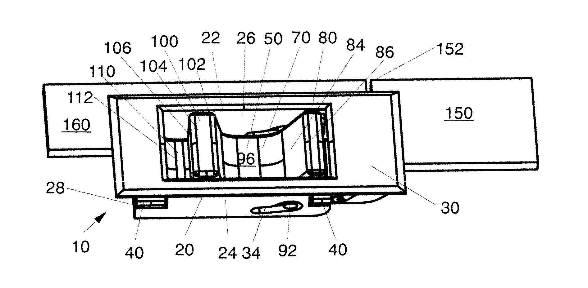
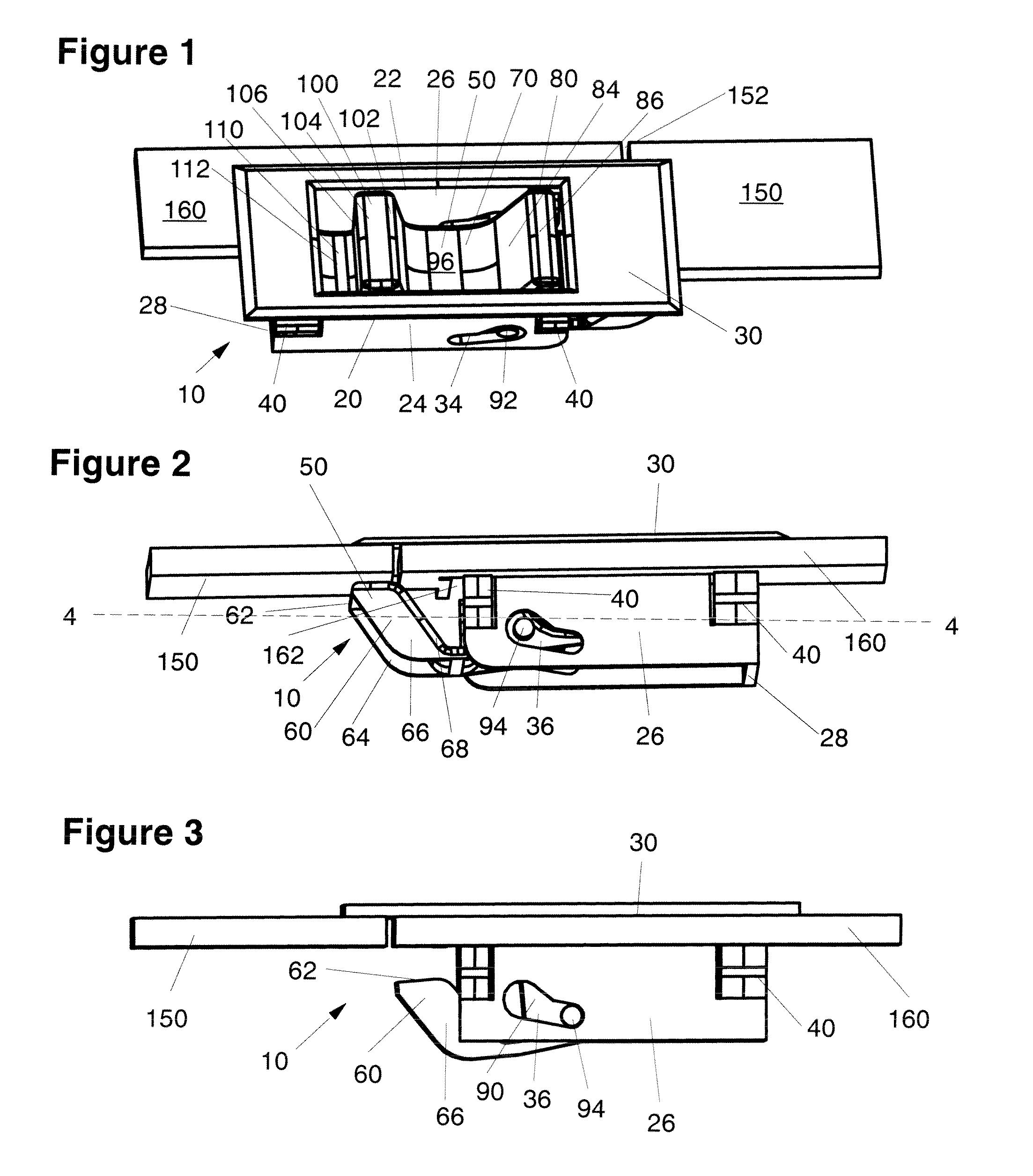
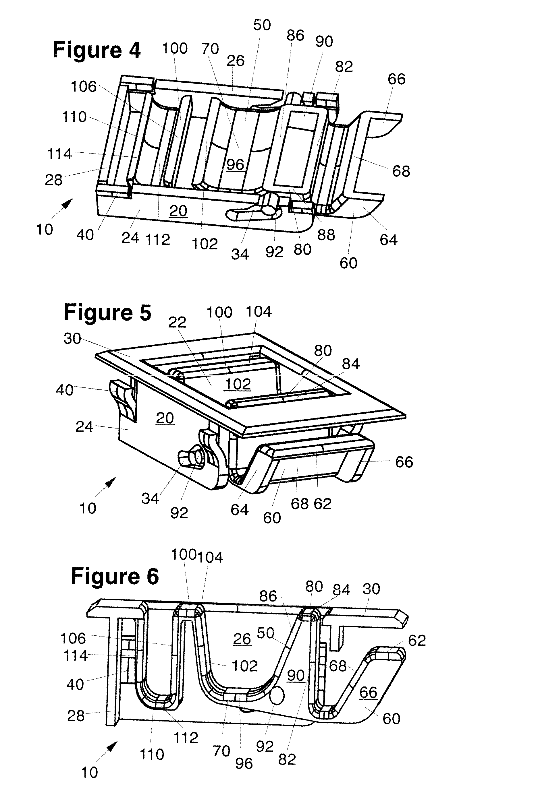
[0029]Referring now to the drawings in detail, wherein like reference numerals indicate like elements throughout the several views, there is shown in FIG. 1 a perspective view of a slide latch 10 of the present invention, the slide latch 10 being shown mounted in a panel or door 160, and in a closed or latched position securing the panel 160 to a frame 150, the panel 160 and frame 150 being shown in a fragmentary section thereof. The latch 10 is preferably formed as a single component by a molding process from a polymeric material having substantial resistance to fatigue from cyclic loading. A particularly preferred polymeric material is acetal resin, available as Delrin® acetal resin from E.I. du Pont de Nemours, Wilmington, Del.

[0030]The latch 10 includes a latch body 20 and a generally rectangular plate 30 from which the latch body 20 downwardly extends. A central, generally rectangular well 22 extends through the plate 30 and into the latch body 20. The latch 10 also includes an...


PUM


Abstract

A sliding-action slam latch includes an integrally molded actuator having a rigid portion and an flexible portion, the flexible portion serving to bias the actuator closed. Pins extending from the rigid portion of the actuator contact guide surfaces on the latch body to limit travel of the actuator.

Description

CROSS-REFERENCE TO RELATED APPLICATIONS[0001]This application is a continuation of U.S. patent application Ser. No. 09 / 619,510, filed Jul. 19, 2000, now abandon which is a non-provisional application of U.S. Provisional Application No. 60 / 144,801, filed Jul. 21, 1999.BACKGROUND OF THE INVENTION[0002]1. Field of the Invention[0003]The present invention relates generally to latching devices, and more particularly to systems for latching hinged doors or panels and the like.[0004]2. Background of the Invention[0005]Various types of latching devices for fastening doors, panels and the like are known.[0006]Door-mounted “slam” latches employ a camming surface on the end of a sliding-bolt element that cooperates with a striker on the door frame to cause a bolt action to secure the door when it is closed against the frame. Such latches are activated to secure the door when the door is merely pushed shut or slammed. However, to open the door, operation of the latch mechanism is required to re...

Claims


Application Information

Patent Timeline
Patent Type & Authority Patents(United States)
IPC IPC(8): E05C5/00E05B15/16E05B65/00E05C19/06
CPCE05C19/06E05B65/006E05B2015/1642Y10S292/30Y10S292/11Y10S292/51Y10S292/63Y10T292/0803Y10T292/0886Y10T292/0891Y10T292/0969Y10T292/0997Y10T292/62
Inventor BERG, GERT
Owner SOUTHCO
Why Eureka
Try Eureka