
Shallow undercut concrete anchor

a concrete anchor and undercutting technology, applied in the field of shallow undercutting concrete anchors, can solve the problems of not being able to achieve the prior art anchor solution, and achieve the desired

Active Publication Date: 2021-09-07
BLACK & DECKER INC
View PDF14 Cites 0 Cited by
  • Summary
  • Abstract
  • Description
  • Claims
  • Application Information

AI Technical Summary

Benefits of technology

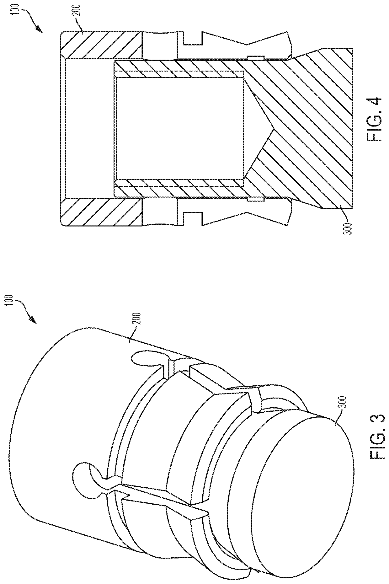
The present invention provides a shallow undercut concrete anchor that can resist high loads with a minimum ¾-inch embedment depth. The anchor system includes a concrete structure with a cylindrical opening and a plug made of a sleeve and a plug. The plug has an increasing diameter portion that engages with the legs of the sleeve to secure the anchor in the concrete hole. The cylindrical opening has a radius and depth of approximately ¾-inch or less. The anchor is installed by inserting the sleeve and plug into the cylindrical opening and then dynamic loading on the plug generates a radially outward force to secure the anchor in the hole.

Problems solved by technology

A steeper curve would be more desirable but could not be achieved with the prior art anchor solution.

Method used


Image

  • Shallow undercut concrete anchor
  • Shallow undercut concrete anchor
  • Shallow undercut concrete anchor

Examples


Embodiment Construction

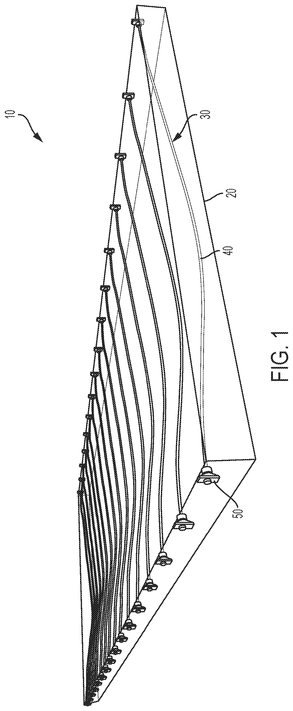
[0035]FIG. 1 shows a post stressed concrete slab unit 10. Slab unit 10 includes a volume (e.g., a rectangular volume) of poured and cured concrete 20 and a plurality of tension wires 30 passing through the concrete volume 20. An individual wire 40 may be disposed at different depths in the direction of thickness of the slab based on loads expected to be experienced at particular areas of the slab when installed. Wires anchors 50 are positioned at outer surfaces of concrete 20 and tension of wires 30 may be adjusted there. With respect to the top and bottom outer surfaces of the concrete slab 20, wire 40 may be positioned within 1 or 2 inches of the outer surfaces of the concrete.

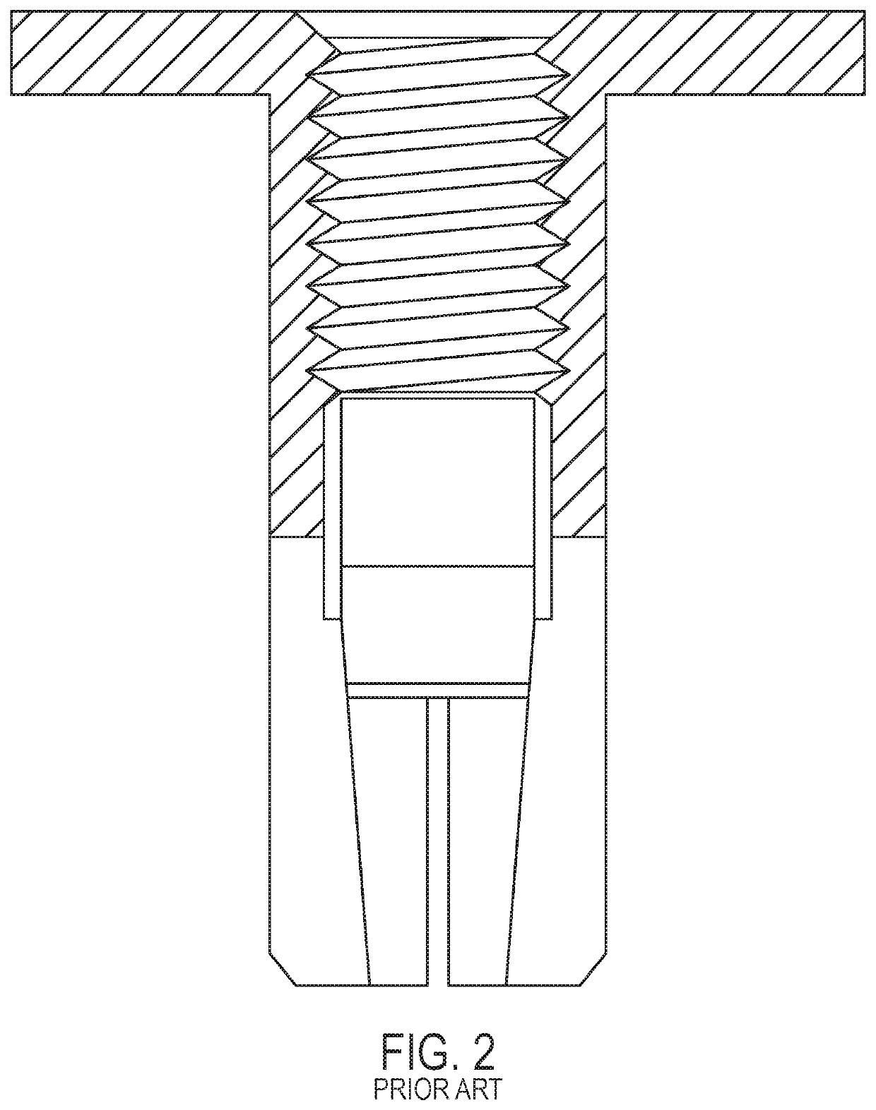
[0036]Some post cast anchors are used in PT slabs today. For example mini drop-in anchors with the following characteristics are used.

[0037]

Thread Diameter [in.]¼″⅜″½″Drill Bit Diameter [in.]⅜½⅝Embedment depth [in.]⅝ (16 mm)¾1 (25.4 mm)Threaded Depth [in.]⅜ 13 / 32⅝Installation Torque [ft-lbs]3510

[0038]These m...


PUM


Abstract

A concrete anchor capable of resisting large loads while requiring minimal embedment depth. The system includes a concrete structure including a cylindrical opening in the concrete surface thereof. The system also uses an anchor which includes a sleeve and a plug. The sleeve includes at least two legs extending toward a first end of the sleeve. The plug includes an increasing diameter portion disposed toward a first end of the plug. The plug includes a locking opening. After installation, legs of the sleeve extend radially outward past the wall and the increasing diameter portion prevents inward movement of the legs to lock the sleeve and the plug in turn in the concrete cylindrical opening. Furthermore, dynamic loading on the plug via the locking opening when the anchor is in use generates a dynamic radially outward force on the legs to secure the anchor in the concrete hole.

Description

CROSS-REFERENCE TO RELATED APPLICATIONS[0001]This is a continuation application of PCT / US2016 / 065508, filed Dec. 8, 2016, which incorporates by reference and derives priority from U.S. Provisional Application No. 62 / 265,212 filed on Dec. 9, 2015.BACKGROUND OF THE INVENTION[0002]Post-tensioned (PT) slabs are typically flat slabs, band beam slabs or ribbed slabs. PT slabs offer the thinnest slab type, as the tensile stress to which the slab is exposed is limited by a compressive wire system. Longer spans can be achieved due to pre-stress, which can be used to counteract deflections. The slabs are pre-stressed by cables / wires that pass through the slabs.[0003]PT slabs are becoming more widely used for a number of reasons. Slabs can be thinner which will usually result in cost savings at least as a result of using less cement. In addition, less material necessarily means that the slabs are more environmentally friendly. Thinner lighter slabs lend to faster and easier construction / erecti...

Claims


Application Information

Patent Timeline
Patent Type & Authority Patents(United States)
IPC IPC(8): E04C5/12B25D17/02E04B5/32F16B13/08B23B51/08F16B13/06F16L3/00
CPCF16B13/0858B23B51/08B25D17/02E04C5/122F16B13/06F16B13/0825F16B13/0841B23B2226/75B25D2222/72E04B5/32E04B2103/02F16L3/00
Inventor PREGARTNER, THILOCERBONE, MARKCHAMBERLAIN, MATTHEW
Owner BLACK & DECKER INC
Learn More