
Spiral welded pipe machine socket ring positioning device

A positioning device and socket ring technology, which is applied in auxiliary devices, welding equipment, auxiliary welding equipment, etc., can solve the problems of axis deviation between the socket plate and the core mold cylinder, weak welding of the steel plate and the socket ring, and affecting product quality. Achieve the effects of simple structure, convenient operation and improved positioning effect

Active Publication Date: 2015-12-09
JIANGSU JIANGYANG BUILDING MATERIAL MACHINERY
View PDF10 Cites 0 Cited by
  • Summary
  • Abstract
  • Description
  • Claims
  • Application Information

AI Technical Summary

Problems solved by technology

[0003] Before the spiral welded pipe is produced, the socket ring is usually placed on the core mold cylinder. The traditional method is to rely on an external positioning block to laterally position the socket ring. In the process of rolling the pipe, due to mechanical vibration and other reasons , the spigot ring will move inward to a certain extent, which will lead to problems such as weak welding between the steel plate and the spigot ring when the pipe making is about to end, and the axis deviation between the spigot plate and the core mold cylinder. affect the quality of the product

Method used


Image

  • Spiral welded pipe machine socket ring positioning device

Examples


Embodiment Construction

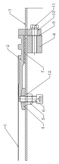
[0016] The present invention will be further elaborated below in conjunction with the accompanying drawings.

[0017] like figure 1 Shown:

[0018] The socket ring positioning device of the spiral welded pipe machine consists of socket ring 2, outer positioning block 10, core mold cylinder body 3, special limit nut 4, inner hexagonal limit bolt 6, hexagon nut 5, socket ring positioning block 8, and adjusting gasket 9. Composed of hexagonal head bolts 11, etc., the mandrel shell is provided with a horse trough 12, the special limit nut, the inner hexagonal limit bolt, and the hexagonal nut form the forward adjustable device of the socket ring, and the inner hexagonal limit bolt is sleeved on the In the trough set on the core mold cylinder, the special limit nut and the hex nut are fixed on the core mold cylinder. The special limit nut is in contact with the front and lower end surface of the socket ring. The upper plane of the special limit nut is inclined. The wedge surface,...


PUM


Abstract

The invention relates to a spiral pipe welder spigot ring positioning device and belongs to the technical field of spiral reel pipe welders. The device comprises a spigot ring, an outer positioning block, a core mould cylinder body, a limit special nut, an inner hexagonal limit bolt, a hexagonal nut, a spigot ring positioning block, an adjusting gasket, a hexagonal head bolt and a cushion block, wherein a spigot ring front adjustable device is formed by the limit special nut, the inner hexagonal limit bolt and the hexagonal nut and is fixedly arranged on the core mould cylinder body through the limit special nut and the hexagonal nut, a spigot ring back positioning device is formed by the spigot ring positioning block, the adjusting gasket and the outer positioning block, the spigot ring positioning block is welded on the core mould cylinder body, and the cushion block is arranged between the front upper end surface of the spigot ring and the core mould cylinder body. The spigot ring can be accurately positioned and tightly clamped through the spigot ring front adjustable device and the spigot ring back positioning device. The spiral pipe welder spigot ring positioning device avoids the inward movement of the spigot ring due to mechanical vibration when a spiral welded pipe is produced, the coaxial line of the spigot ring and the core mould cylinder body is guaranteed, a steel plate and the spigot ring are firm in welding, and the quality of a product is improved.

Description

technical field [0001] The invention relates to a PCCP large-caliber concrete pipe thin-wall steel cylinder spiral coil pipe welding machine, in particular to the positioning control of a spigot ring, and belongs to the technical field of spiral coil pipe welding pipe machines. Background technique [0002] As early as 1888, the United States had developed and applied the spiral welded pipe technology. Around the 1950s, West Germany, the United Kingdom and other countries made major breakthroughs in the spiral welded pipe technology. So far, all countries have established a large number of spiral welded pipe production enterprises. [0003] Before the spiral welded pipe is produced, the socket ring is usually placed on the core mold cylinder. The traditional method is to rely on an external positioning block to laterally position the socket ring. In the process of rolling the pipe, due to mechanical vibration and other reasons , the spigot ring will move inward to a certain ...

Claims


Application Information

Patent Timeline
Patent Type & Authority Patents(China)
IPC IPC(8): B23K37/04
CPCB21C37/122
Inventor 何国华陈靖芯马祥秦永法陈启银李红周青
Owner JIANGSU JIANGYANG BUILDING MATERIAL MACHINERY
Learn More