Mechanism for deflecting headlamp optical axis without speed reduction gears

a technology of optical axis and headlamp, which is applied in the direction of lighting and heating apparatus, transportation and packaging, lighting support devices, etc., can solve the problems of increasing the number of gears employed and increasing the deflection error, so as to reduce the mechanism and eliminate the use of speed reduction gears. , the effect of deteriorating accuracy

Inactive Publication Date: 2006-11-28
MINEBEA CO LTD
View PDF17 Cites 3 Cited by
  • Summary
  • Abstract
  • Description
  • Claims
  • Application Information

AI Technical Summary

Benefits of technology

[0008]In order to achieve the object of the present invention, according to a first aspect of the present invention, a mechanism for deflecting a headlamp optical axis comprises a connecting lever, a bracket, a motor, a motor attaching member, and a traveling block. The connecting lever defines a first end and a second end, and has the first end fixed to a headlamp assembly which emits light and which is mounted on an automotive vehicle, and a prescribed portion between the first and second ends of the connecting lever is attached in a horizontally movable manner to one predetermined portion of an outside frame which either encloses the headlamp assembly or constitutes a body of the automotive vehicle. The bracket has its first end fixedly attached to another predetermined portion of the outside frame. The motor includes a motor body which includes a rotating mechanism, and a rotary shaft which has its rearward portion inserted through the motor body, has its frontward portion sticking out from the motor body, and which has a spiral screw formed on the frontward portion thereof. The motor attaching member is for attaching the motor to a second end of the bracket such that the motor can move horizontally. And, the traveling block is shaped substantially hollow-cylindrical, has a screw formed on its inner circumference so as to threadedly engage with the spiral screw formed on the rotary shaft, has its outer circumference attached to the second end of the connecting lever in a horizontally movable manner, and is caused to travel along the rotary shaft when the rotary shaft rotates with respect to the motor body. Thus, since no gears are employed to reduce the rotation supped of the rotary shaft, it is not required to manage those gears with respect to procurement, quality, assembly, cost, and the like, and deterioration in accuracy resulting from the employment of the speed reduction gears can be eliminated.
[0009]In the first aspect of the present invention, the headlamp assembly may emit light from its front surface and may have its rear portion fixed to the connecting lever. Since the motor, the traveling block, and the connecting lever are adapted to move horizontally while the connecting lever is attached to the rear end portion of the headlamp assembly, the entire height of the headlamp assembly and the mechanism can be reduced compared with a conventional mechanism in which an actuator is disposed under a headlamp assembly. This increases the degree of design freedom for an automotive vehicle.
[0010]In the first aspect of the present invention, the connecting lever, the bracket, the motor, the motor attaching member, and the traveling block may be housed in one chassis. Consequently, a satisfactory dust-proof construction can be achieved.
[0011]In the first aspect of the present invention, the motor may be a stepping motor. Since the stepping motor can provide a precise rotation angle control, the deflection of a headlamp optical axis can be precisely controlled.
[0012]In the first aspect of the present invention, the motor attaching member may be constituted by a front end plate which has a center hole formed at its main section and allowing the rotary shaft to go therethrough, includes arm sections formed at rim portions of the main section and bent toward the rear end of the motor body, and which has the main section attached to a portion of the motor body having the rotary shaft sticking out, and the motor may be attached such that the arm sections of the front end plate are movably jointed to the second end of the bracket. With the front end plate structured as above, motors originally intended for other applications can be flexibly attached to the mechanism. This results in volume efficiency thus reducing the production cost.

Problems solved by technology

Also, increase in the number of gears employed involves a risk of increasing deflection error.
The same problems are seen in a mechanism for swinging an object, which employs a plurality of speed reduction gears in addition to a motor.

Method used


Image

  • Mechanism for deflecting headlamp optical axis without speed reduction gears
  • Mechanism for deflecting headlamp optical axis without speed reduction gears
  • Mechanism for deflecting headlamp optical axis without speed reduction gears

Examples


Embodiment Construction

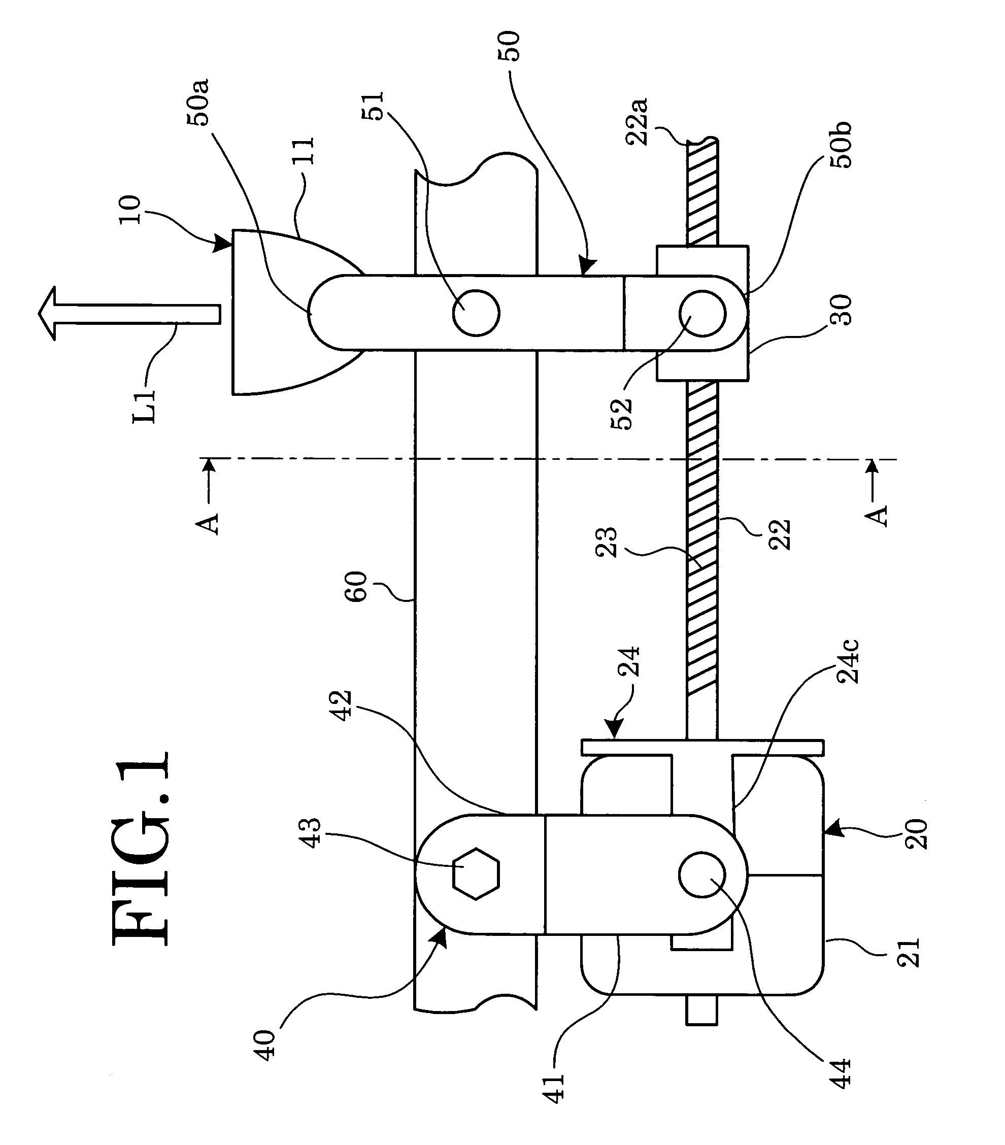
[0020]A mechanism for deflecting a headlamp optical axis according to an embodiment of the present invention will hereinafter be described with reference to FIGS. 1 to 4A and 4B.

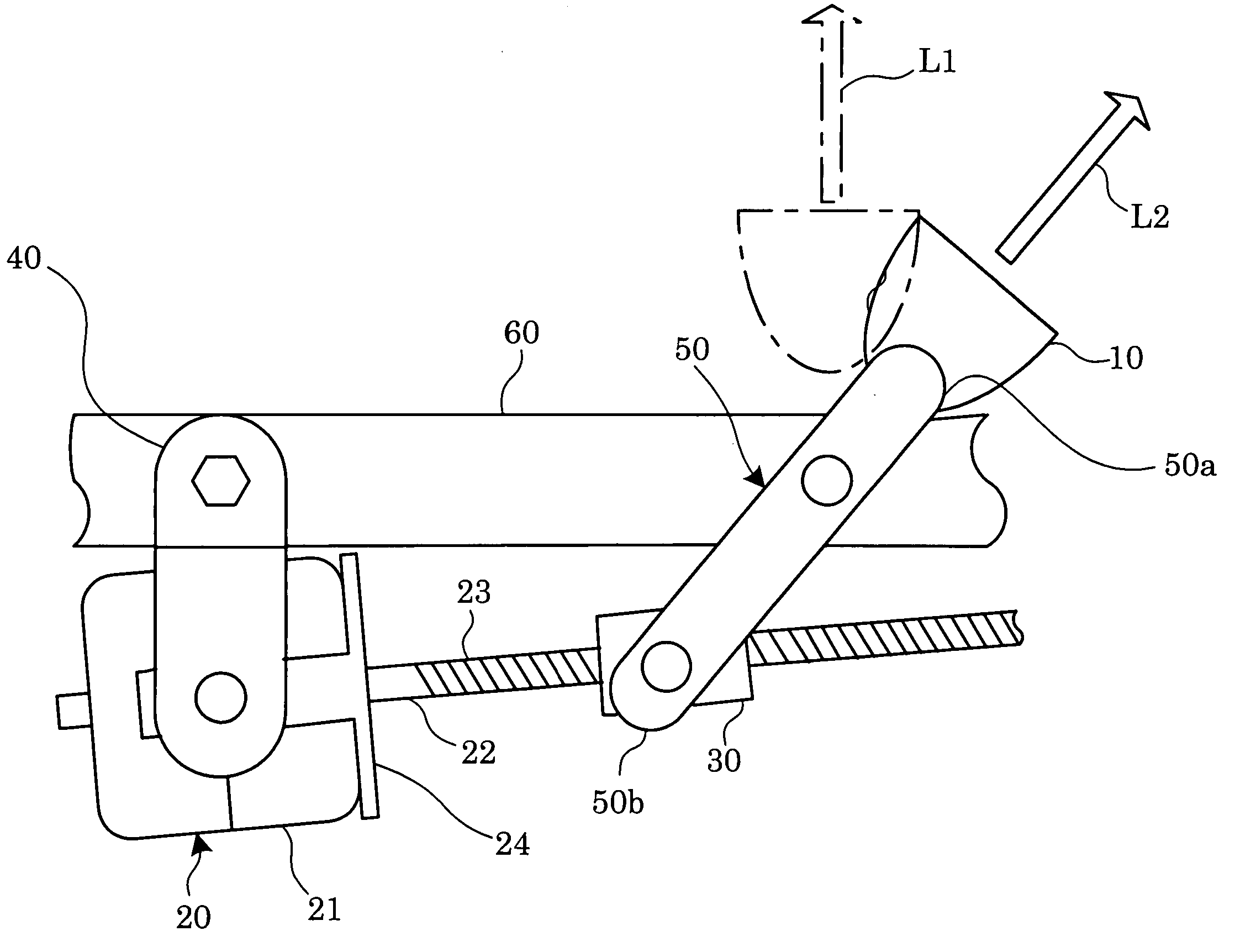
[0021]A mechanism for deflecting a headlamp optical axis shown in FIG. 1 is mounted on an automotive vehicle, and adapted to swing a headlamp assembly 10 in the horizontal direction. The mechanism comprises a stepping motor 20, a traveling block 30, a bracket 40, and a connecting lever 50. The headlamp assembly 10, the stepping motor 20, the traveling block 30, the bracket 40, and the connecting lever 50 are housed in a chassis (not shown).

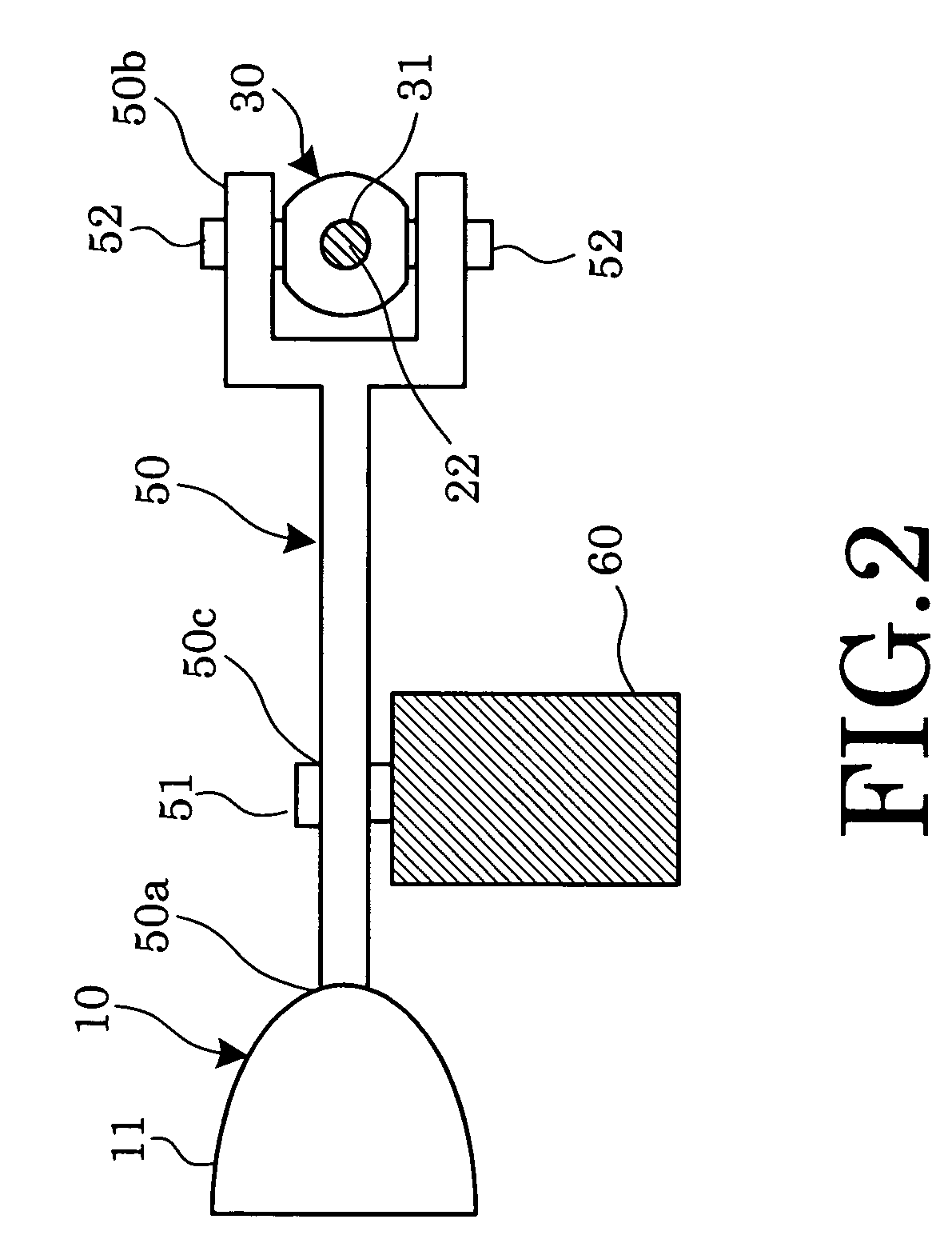
[0022]The headlamp assembly 10 includes a lamp (not shown), and a reflector 11 to enclose the lamp from behind and to reflect light emitted from the lamp frontward. As shown in FIG. 2, the connecting lever 50 has a first end 50a thereof attached by, for example, welding to a rear portion of the headlamp assembly 10, specifically to a rear portion of the reflector 11.

[0023]...


PUM


Abstract

A mechanism for deflecting a headlamp optical axis comprises a connecting lever, a bracket, a stepping motor, a front end plate, and a traveling block. The bracket is attached to an outside frame constituting an automotive vehicle body, and the stepping motor is attached to the bracket in a horizontally movable manner. The stepping motor has a rotary shaft which has a screw formed thereon and engaging threadedly with the traveling block. The connecting lever is attached to the outside frame in a horizontally movable manner. In the mechanism structured above, when the rotary shaft rotates, the traveling block is caused to travel along the rotary shaft thereby causing the both ends of the connecting lever to move in respective arc paths, whereby an optical axis of a headlamp attached to one of the both ends of the connecting lever is deflected.

Description

BACKGROUND OF THE INVENTION[0001]1. Field of the Invention[0002]The present invention relates to a mechanism for deflecting a headlamp optical axis, which does not use speed reduction gears, and further to a mechanism for swinging an object, which does not use speed reduction gears.[0003]2. Description of the Related Art[0004]Some headlamps mounted on the recent automotive vehicles come in an AFS (Adaptive Front-lighting System). The AFS allows light beam direction to be adjusted in response to driving conditions by swinging the entire headlamp assembly. A mechanism for deflecting a headlamp optical axis is disclosed, for example, in Japanese Patent Applications KOKAI Publications Nos. 2001-277938 (Paragraphs 0032 to 0034, FIG. 7 therein), 2002-326536 (FIG. 4 therein), and 2002-234382 (Paragraph 0009, FIG. 4 therein), which comes in an AFS, and which deflects a headlamp optical axis horizontally in accordance with degree of steering angle.[0005]In a mechanism to deflect a headlamp o...

Claims


Application Information

Patent Timeline
Patent Type & Authority Patents(United States)
IPC IPC(8): F21V19/02B60Q1/12B60Q1/076F21V14/04
CPCB60Q1/076F21S48/1757F21S41/675
Inventor SUZUKI, YUZURUMATSUSHITA, KUNITAKEBELAVSKY, SYLVIE
Owner MINEBEA CO LTD
Why Eureka
Try Eureka