Fuel cell containing a cathode diffusion layer having a fabric structure

a fuel cell and fabric structure technology, applied in the field of fuel cells, can solve the problems of deterioration in power generation performance, inadequate control of diffusion layer thickness, and satisfactorily responding, and achieve the effect of miniaturizing the fuel cell system and maintaining high power generation performan

Inactive Publication Date: 2012-09-25
SHARP KK
View PDF7 Cites 0 Cited by
  • Summary
  • Abstract
  • Description
  • Claims
  • Application Information

AI Technical Summary

Benefits of technology

[0020]In order to prevent occurrence of such malfunction in controlling the thickness of the diffusion layer due to uneven distribution of water, it is necessary to dispose the water-absorbable resin in plural positions so as to realize uniform dispersion over the power generation area. This increases the regions that do not contribute to power generation within the power generation area, and results in the problem of deterioration in power generation performance.
[0022]In light of the above, it is an object of the present invention to provide a fuel cell capable of maintaining high power generation performance even in the case of change in the external environment, while enabling miniaturization of a fuel cell system.
[0025]Preferably, in the fuel cell of the present invention, gas permeability of the cathode diffusion layer increases as the water absorption amount of the water-swellable fiber increases.
[0033]According to the present invention, it is possible to provide a fuel cell capable of maintaining high power generation performance even in the case of change in the external environment, while enabling miniaturization of a fuel cell system.

Problems solved by technology

Therefore, when extreme excess or shortage of the water amount occurs only in the region where the water-absorbable resin is disposed, it is impossible to appropriately control the thickness of the diffusion layer, and it is impossible to satisfactorily respond to the change in the external environment, leading to the problem of deterioration in power generation performance.
This increases the regions that do not contribute to power generation within the power generation area, and results in the problem of deterioration in power generation performance.
Further, in order to prevent occurrence of the aforementioned malfunction, it is necessary to dispose the water-absorbable resin to penetrate the electrolyte membrane, leading to the problem that the sealing structure is complicated.

Method used


Image

  • Fuel cell containing a cathode diffusion layer having a fabric structure
  • Fuel cell containing a cathode diffusion layer having a fabric structure
  • Fuel cell containing a cathode diffusion layer having a fabric structure

Examples


example 1

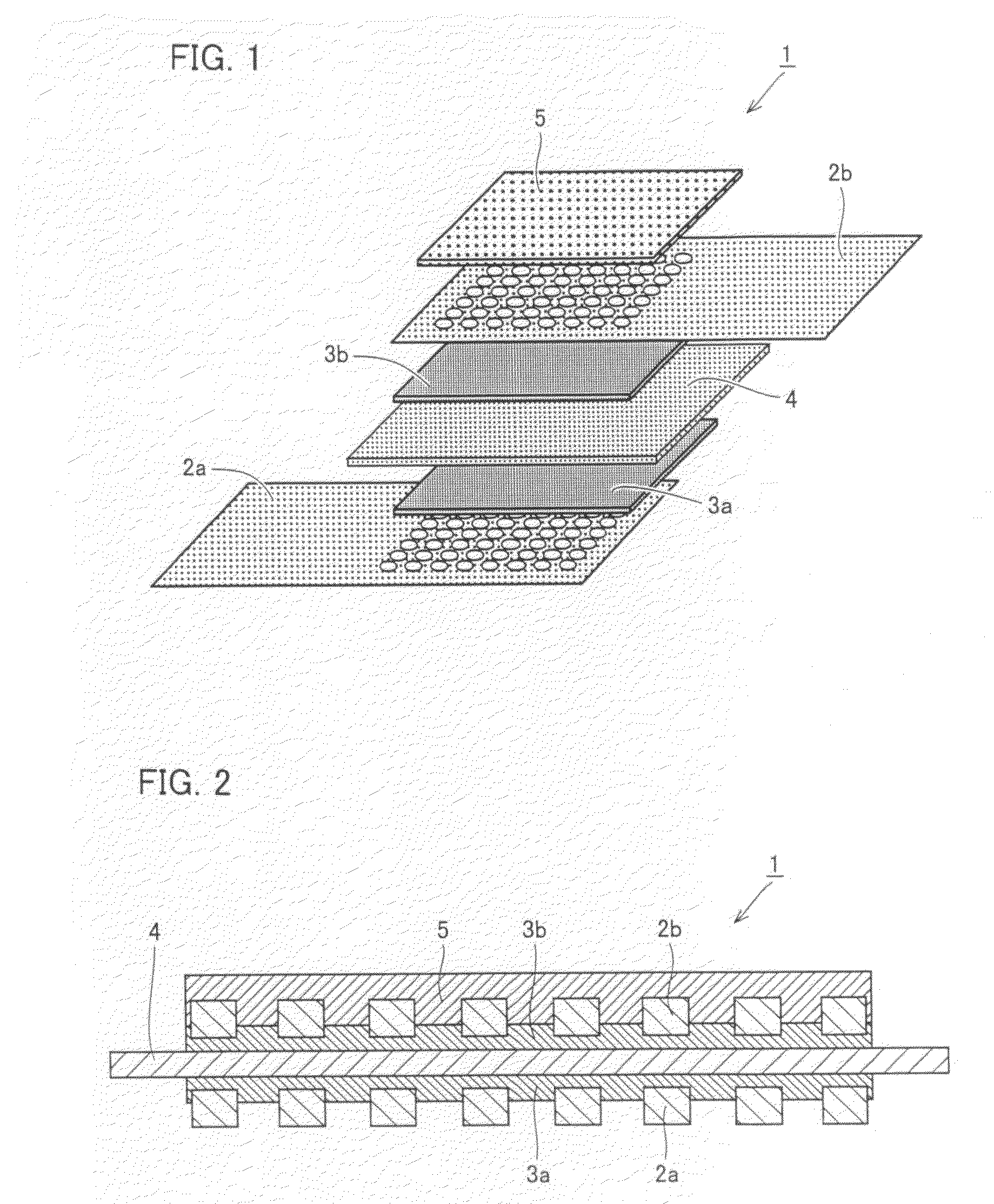
[0104]In the present example, a fuel cell having a structure similar to that of fuel cell 1 shown in FIG. 1 (fuel cell of Example 1) was produced. In the following, a producing method of the fuel cell of Example 1 will be described.

[0105]First, as electrolyte membrane 4, Nafion (trademark) 117 (available from Du Pont) of 40 mm wide×40 mm long, having a thickness of about 175 μm was prepared.

[0106]Next, catalyst-carrying carbon particles (TEC66E50 available from Tanaka Kikinzoku) consisting of Pt particles, Ru particles and carbon particles having a Pt carrying amount of 32.5% by mass and an Ru carrying amount of 16.9% by mass, an alcohol solution containing 20% by mass of Nafion (trademark) (available from Aldrich), isopropanol, and alumina balls were charged in a mass ratio of 0.5:1.5:1.6:100 into a Teflon (trademark) container, and mixed at 500 rpm for 50 minutes using a stirrer, to produce an anode catalyst paste.

[0107]On the other hand, a cathode catalyst paste was produced in a...

example 2

[0130]In the present Example, a fuel cell having a similar structure as fuel cell 1 having a structure shown in FIG. 5 (fuel cell of Example 2) was produced.

[0131]As anode diffusion layer 6, carbon paper (35BC available from SGL carbon) cut into a square shape of 23 mm wide×23 mm long was prepared. Then anode diffusion layer 6 formed of this carbon paper was overlaid at the same position with anode catalyst layer 3a from outside of gold mesh which was to be anode conductive layer 2a. Here, a microporous layer of anode diffusion layer 6 was overlaid so that it faces with the side that is in contact with anode conductive layer 2a.

[0132]Then, a stainless spacer of 600 μm thick was arranged, and hot press was executed to join anode diffusion layer 6 with anode conductive layer 2a.

[0133]Further, as fuel permeation layer 7, a hydrocarbon-based solid polymer membrane (available from TOKUYAMA) was prepared, and fuel permeation layer 7 was arranged outside anode diffusion layer 6 in such a...


PUM

PropertyMeasurementUnit
temperatureaaaaaaaaaa
proton conductivityaaaaaaaaaa

Abstract

A fuel cell including an anode conductive layer, an anode catalyst layer, an electrolyte membrane, a cathode catalyst layer, a cathode conductive layer, and a cathode diffusion layer stacked in this order, in which the cathode diffusion layer has a fabric structure in which a water-swellable fiber and a non-water-swellable fiber are arranged. Preferably, in the fabric structure, the water-swellable fiber is arranged in either one of a warp and a weft. Preferably, gas permeability of the cathode diffusion layer increases as the water absorption amount of the water-swellable fiber increases.

Description

[0001]This nonprovisional application is based on Japanese Patent Application No. 2007-015145 filed with the Japan Patent Office on Jan. 25, 2007, the entire contents of which are hereby incorporated by reference.BACKGROUND OF THE INVENTION[0002]1. Field of the Invention[0003]The present invention relates to a fuel cell, and in particular, to a fuel cell capable of maintaining high power generation performance even when the external environment changes, and enabling miniaturization of a fuel cell system.[0004]2. Description of the Background Art[0005]In recent years, fuel cells as compact power sources for portable electronic devices that support an information society have been much expected because of their potential ability of offering high electrical efficiency as a single power supply. A fuel cell is a chemical cell that supplies a portable electronic device or the like with electrons by utilizing such an electrochemical reaction that a fuel such as hydrogen gas or a methanol a...

Claims


Application Information

Patent Timeline
Patent Type & Authority Patents(United States)
IPC IPC(8): H01M8/10
CPCH01M4/926H01M8/1002H01M8/1011H01M2008/1095Y02E60/523H01M8/1007Y02E60/50
Inventor KAMBARA, HIRONORI
Owner SHARP KK
Why Eureka
Try Eureka