Radiation sensitive recording plate with orientation identifying marker, method of making, and of using same

a technology of orientation identification and recording plate, applied in the field of image processing, can solve the problems of inherently unambiguous digital images produced using cameras with detectors such as charge-coupled devices (ccds) that are sensitive to exposure from one side only, and the problem of dental or medical diagnostic images produced on conventional film is somewhat more complicated, and the film thus constructed cannot be oriented on the basis of which side has an emulsion

Inactive Publication Date: 2006-11-28
KAY GEORGE W
View PDF19 Cites 94 Cited by
  • Summary
  • Abstract
  • Description
  • Claims
  • Application Information

AI Technical Summary

Problems solved by technology

Likewise, digital images produced using cameras with detectors such as charge-coupled devices (CCDs) that are sensitive to exposure from one side only are inherently unambiguous.
The problem is somewhat more complicated for dental or medical diagnostic images produced on conventional film.
However, film thus constructed cannot be oriented on the basis of which side has an emulsion.
However, this clear and unambiguous outcome relies either upon the mechanical features noted above, or upon the X-ray technician properly loading the cassette and placing the orienting labels, followed by exposing from the correct side.
Because intraoral films must be small enough to be positioned within the mouth, there is little room available for the types of labels described above.
If an exposure is made from the wrong side, the resulting image is recognizably undiagnostic because of its degradation caused by the radiopaque backing contained within the packet.
The degradation of the image evidencing improper exposure orientation of the film, which results in the reversal of the diagnostic image when the bump feature is used to orient the image, is, however, immediately obvious to the viewer, assuring that mistaken identification of features in the image is highly unlikely and traceable.
The image orientation issues noted above with respect to conventional film; however, as well as new image orientation problems, for example resulting from the use of image processing software, manifest themselves in the use of such radiosensitive plates.
Incomplete references or markers, as discussed below are incorporated into the existing systems; however, none of the systems are unambiguous, permanent, or complete by virtue of their design.
Therefore, the two sides of the body (or mouth) can be confused by the viewer of the image, resulting in erroneous diagnosis and / or treatment.
However, the problem occurs in connection with many physiological structures as a result of the inherent symmetry present in most biological systems, particularly humans and animals.
However, such a consistent usage is not guaranteed.
Although recommended, and consistent with best practice, such a consistent exposure of the plate from the sensitive side is not guaranteed either in the loading of the plate into the sleeve or in its placement during exposure itself.
Digital plate technology in its current form does not assure that the orientation of the image can be ascertained.
However, no unambiguous marker of the exposure orientation exists within the image.
1. If only one image is available for viewing independently of other patient information, the viewer will not be able to identify the correct orientation of the image, except by making an assumption that it was exposed from the “front side”.
2. If a technician is consistently making the error of exposing the films from the “back side”, unknown to the viewer, the viewer will conclude when comparing images that images (in fact) exposed and oriented correctly are incorrectly oriented (which is not factually correct), thus compounding the problem.
3. A disgruntled or incompetent employee can wreak havoc with the records without anyone realizing it, or having a way of tracing the problem by using software to alter the apparent orientation of images in the records.
4. A person with fraudulent intent can expose the plate intentionally from the “back side” in order to make the image appear as though it depicts the opposite side of the body.

Method used


Image

  • Radiation sensitive recording plate with orientation identifying marker, method of making, and of using same
  • Radiation sensitive recording plate with orientation identifying marker, method of making, and of using same
  • Radiation sensitive recording plate with orientation identifying marker, method of making, and of using same

Examples


second embodiment

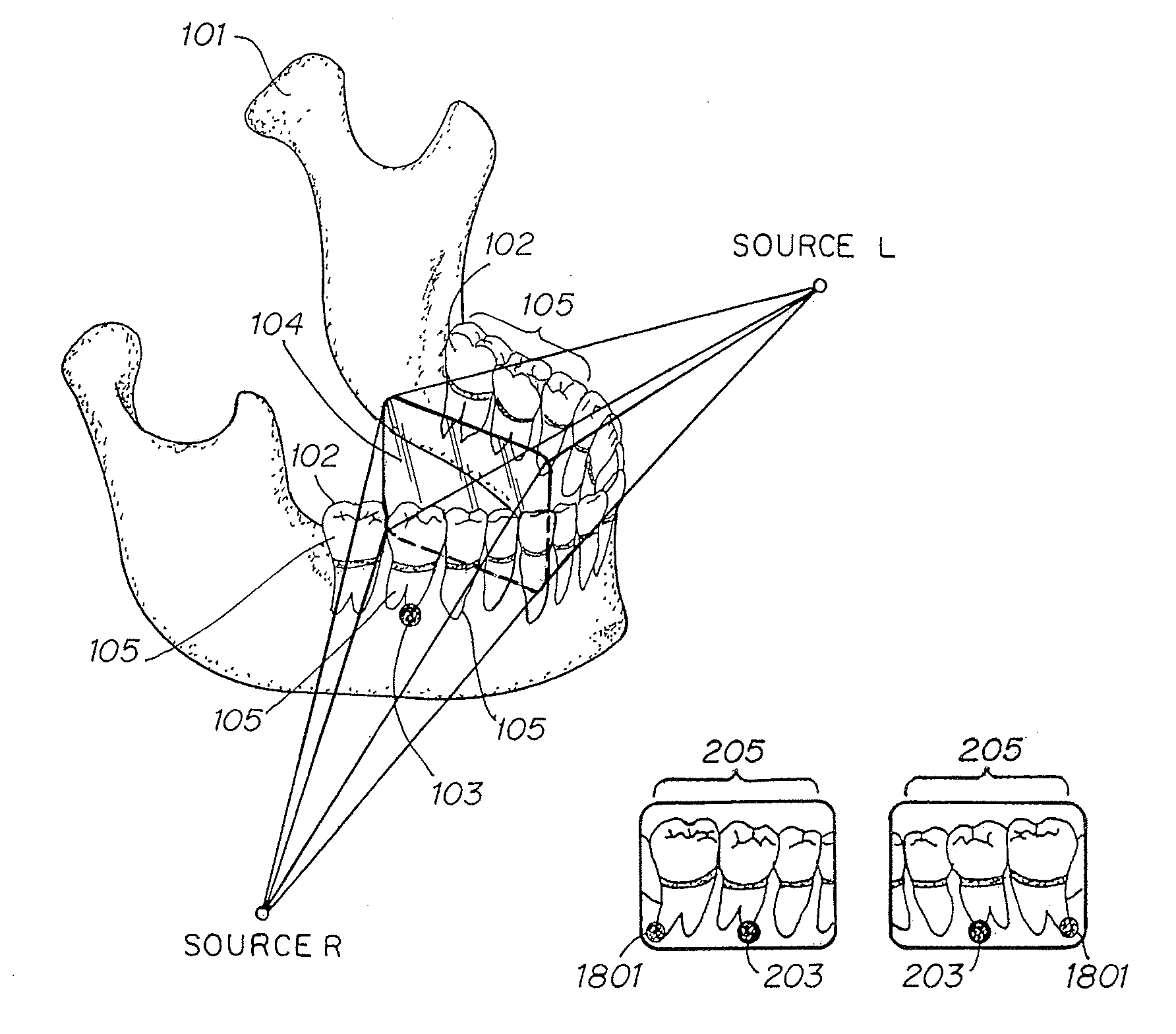
[0108]If the plate is marked by both a “front side” marker and a “back side” marker, as described in connection with the second embodiment, the direction of exposure of the plate is unambiguously recorded in the image without any intervention or special act by the operator. In addition, the cassette or sleeve in which the plate is placed during exposure can include a radiopaque mark on one or both sides, unambiguously indicating the proper orientation of the cassette or sleeve relative to some absolute reference such as the left side or front of the patient.

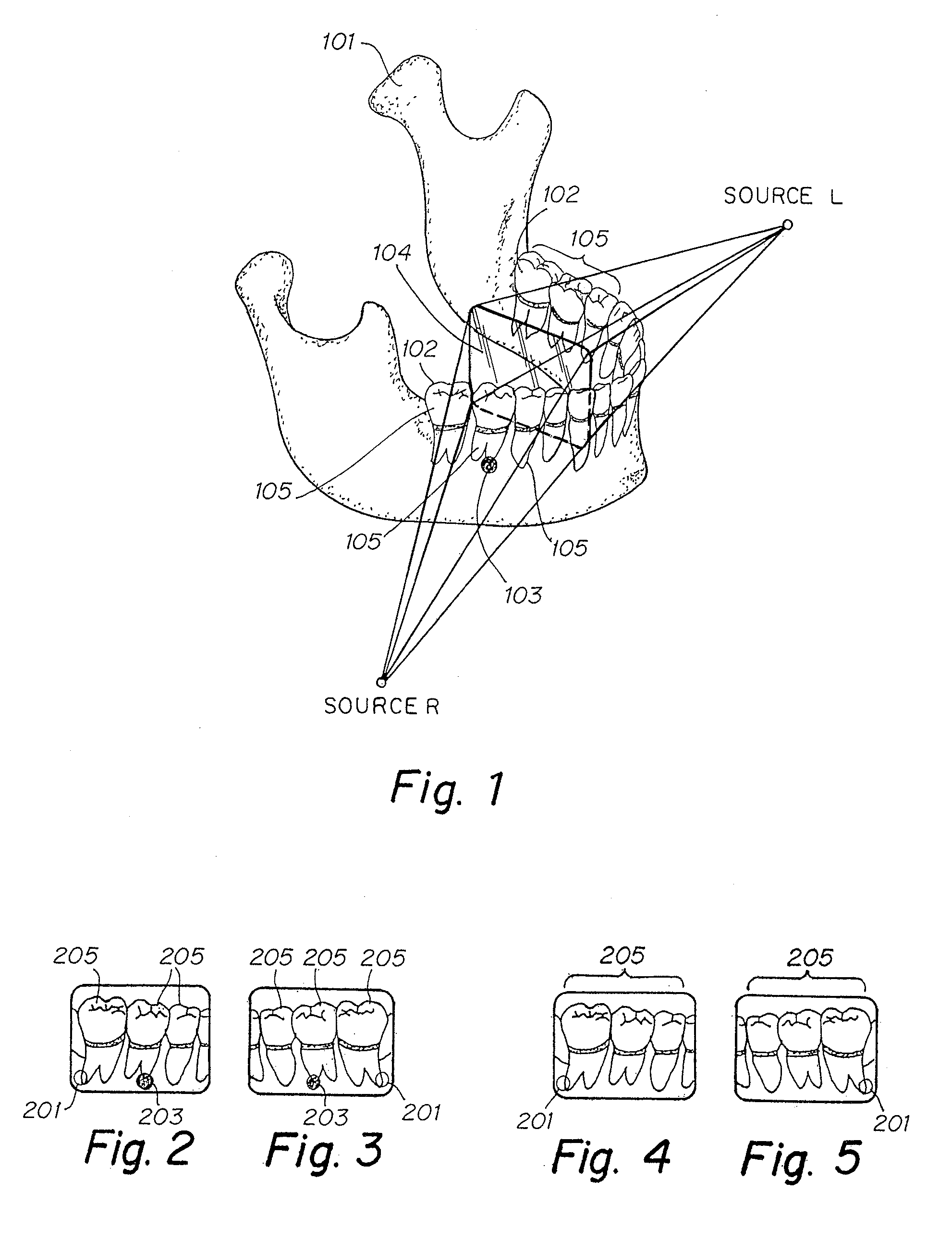
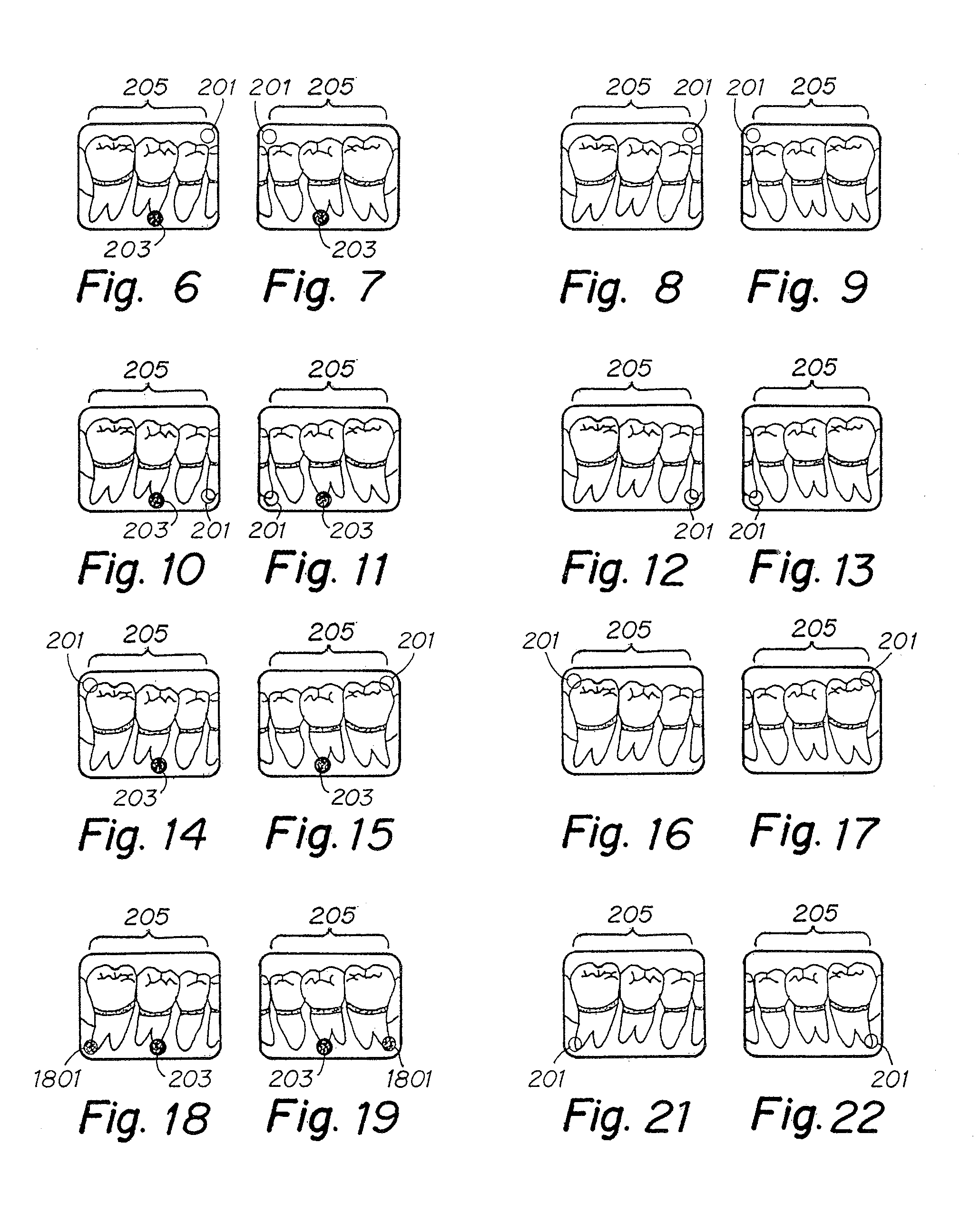
[0109]FIGS. 18, 19, 20 and 21 illustrate four images that can be produced using a digital X-ray plate according to this embodiment of aspects of the invention, exposed from each of two sides, using each of two differently located sources, e.g., positioned at SOURCE L and SOURCE R. This embodiment has an open circle mark on the X-ray sensitive side of the plate, in one corner, and a filled circle mark on the other side of the plat...

third embodiment

[0117]In the invention, shown in FIG. 39, the markers are asymmetric, are asymmetrically placed with respect to the plate surface axes of symmetry, and both “front side” and “back side” markers are employed. In the example, the markers 3901 and 3902 are made in the shape of arrows. Of course, markers 3901 and 3902 could be any suitable directional marker meeting the further requirements described in connection with this embodiment. Let us further suppose that the “front side” marker 3901 is a thin, short, horizontally directed arrow pointing at the right vertical edge of the plate at the lower edge of image 3900, while the “back side” marker 3902 is a solid arrow, also horizontally directed at the lower edge of a “landscape” oriented plate, but pointing away from the vertical edge of the plate of image 3900. For purpose of illustration, by virtue of their size and placement on the opposite sides of plane defined by the plate, the relationship between the markers 3901, 3902 produces ...


PUM

PropertyMeasurementUnit
areasaaaaaaaaaa
areaaaaaaaaaaa
excitation wavelengthaaaaaaaaaa

Abstract

A radiation-recording plate (104) can be constructed and arranged to form an image upon exposure from both a front side and a back side. The plate can include a marker (201) detectable in the image (205) after exposure and indicative of which of the front side and the back side the plate is exposed from. The marker may comprise a medium opaque to the radiation coating a region that does not interfere with reading the image when the plate is exposed from either side, or may be a void in the sensitive layer of the plate. The marker may have horizontal asymmetry about a vertical axis relative to a normal image orientation, or the marker may have vertical asymmetry about a horizontal axis relative to a normal image orientation. The marker may further comprise a front side marker and a back side marker whose appearance in an image on the plate indicates exposure from the front side or the back side respectively. A method of identifying a side from which a radiation-recording plate has been exposed to radiation may comprise: incorporating in the plate (104), in a position that substantially does not interfere with an image area of the plate, a marker (201) whose appearance in the image identifies which side the plate is exposed from; exposing the plate to the radiation; and observing the image (205) for the identification of the side of the plate exposed. A method of making a radiation sensitive plate having at least one radiation sensitive layer may comprise: providing a film sensitive to the radiation on a first side of the radiation sensitive plate; and applying a suspension of a heavy metal in a binder to a region of a second side of the radiation sensitive layer.

Description

CROSS REFERENCE TO RELATED APPLICATION[0001]This application claims priority under 35 U.S.C. § 119(e) to U.S. Provisional Application Ser. No. 60 / 372,323, entitled “METHOD FOR INTERNALLY LABELING THE ORIENTATION OF EXPOSURE OF RADIATION-SENSITIVE PLATES BY PRODUCING A RECOGNIZABLE PATTERN WITHIN THE INFORMATION SET PRODUCED BY SUCH EXPOSURE,” filed on Apr. 12, 2002, and to U.S. Provisional Patent Application Ser. No. 60 / 431,282, entitled “A RADIATION SENSITIVE RECORDING PLATE, A METHOD OF MAKING SAME AND A METHOD OF RECORDING AND ORIENTING IMAGES,” filed on Dec. 6, 2002, and to U.S. patent application Ser. No. 10 / 392,158, entitled “A RADIATION SENSITIVE RECORDING PLATE AND METHOD OF MAKING AND USING SAME,” filed on Mar. 18, 2003, all of which are herein incorporated by reference in their entirety.BACKGROUND[0002]This application relates generally to image processing. More specifically, the application relates to identifying image orientation. Yet more specifically, the application r...

Claims


Application Information

Patent Timeline
Patent Type & Authority Patents(United States)
IPC IPC(8): G03B42/04G01N23/04G03C5/16
CPCA61B6/14G01N23/04G03B42/042G03B42/047G03C5/16
Inventor KAY, GEORGE W.
Owner KAY GEORGE W
Why Eureka
Try Eureka