
Outboard motor shift mechanism

a technology of shifting mechanism and outboard motor, which is applied in the direction of propulsive elements, marine propulsion, vessel construction, etc., can solve the problems of shock, increase the number and weight of components, complicated structure, etc., and achieve the effect of improving operation feel and avoiding increase in number of components and weigh

Inactive Publication Date: 2006-11-28
HONDA MOTOR CO LTD
View PDF18 Cites 9 Cited by
  • Summary
  • Abstract
  • Description
  • Claims
  • Application Information

AI Technical Summary

Benefits of technology

[0011]An object of the present invention is therefore to overcome the foregoing issues by providing a shift mechanism for an outboard motor that improves operation feel, is simply configured to avoid increase in number of components and weight, while avoiding a problem regarding space utilization.
[0012]Another object of the present invention is to provide a shift mechanism for an outboard motor that is simply configured to avoid increase in number of components and weight, while mitigating shock or stress during shift.
[0013]Still another object of the present invention is to provide a shift mechanism for an outboard motor that is simply configured to avoid increase in number of components and weight, while enabling to move the shift rod without using the actuator in case of failure of the actuator.

Problems solved by technology

The add-on system using such an actuator has disadvantages that its structure is complicated, that it adds to the number and weight of the components, and it needs a space for the actuator at the hull.
In this type of clutch, unless the rotation of drive shaft side (forward / reverse gears) and that of driven shaft side (shifter clutch) are in synchronism with each other, projections formed thereon do not fit into mated recesses smoothly at the beginning of shift, thereby causing shock to happen.
With this, the drive train (including the drive shaft, propeller shaft) may have excessive stress.
However, this also has disadvantages that its structure is complicated, that it adds to the number and weight of the components.

Method used


Image

  • Outboard motor shift mechanism
  • Outboard motor shift mechanism
  • Outboard motor shift mechanism

Examples


first embodiment

[0036]An outboard motor shift mechanism according to the invention will now be explained with reference to the attached drawings.

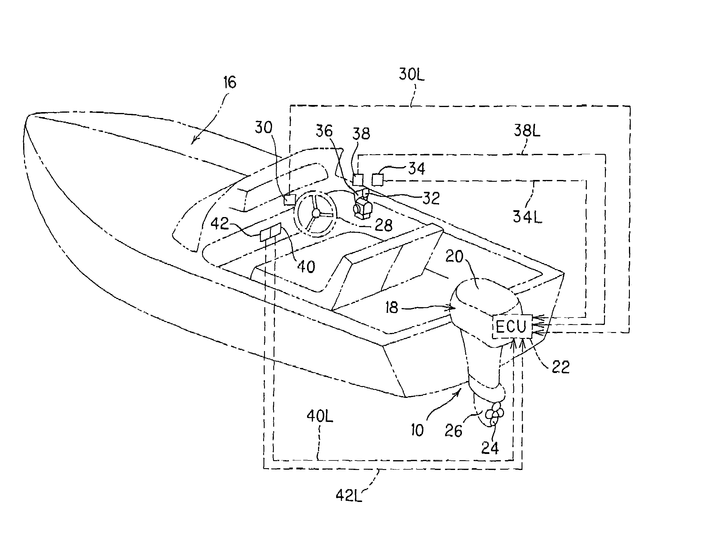
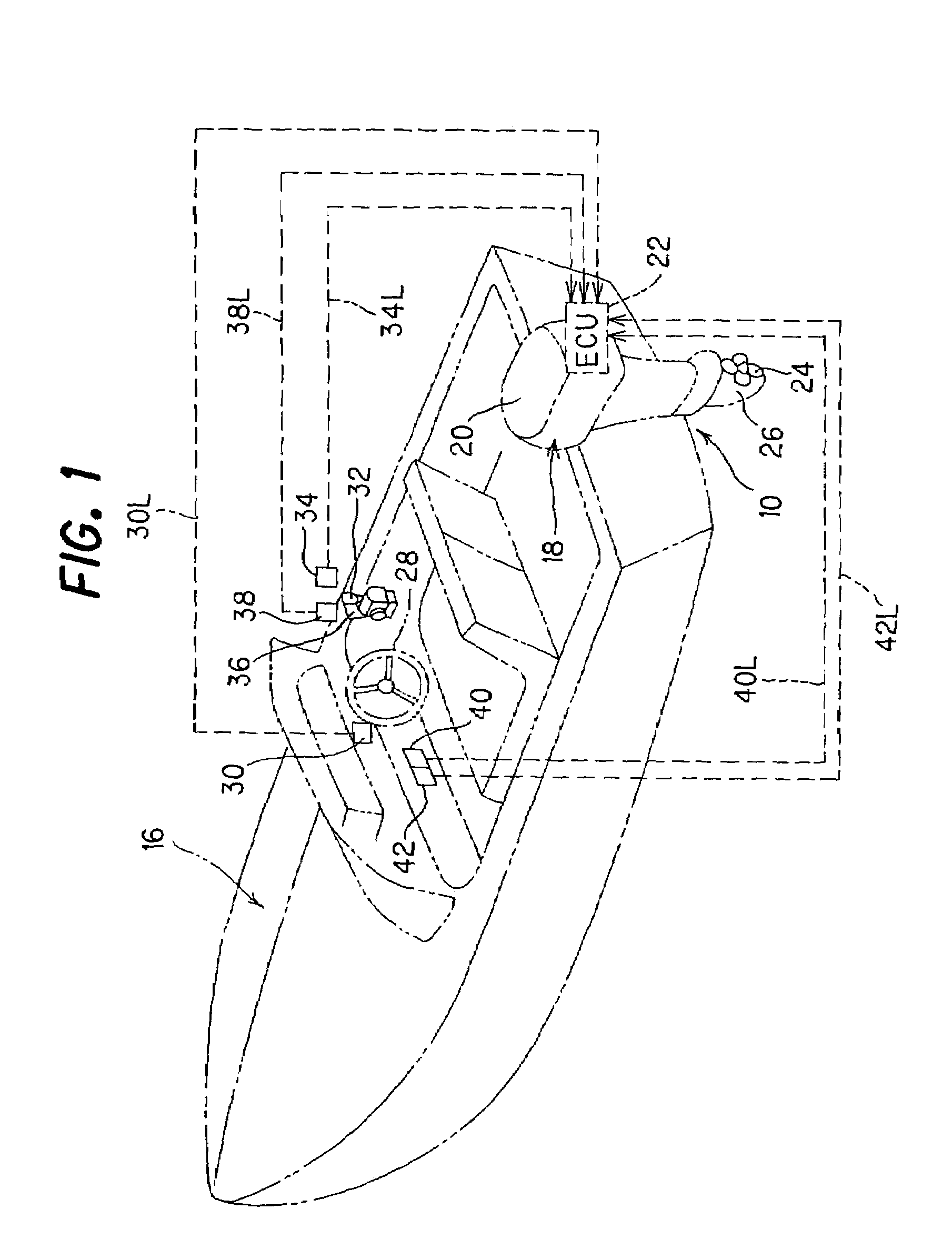
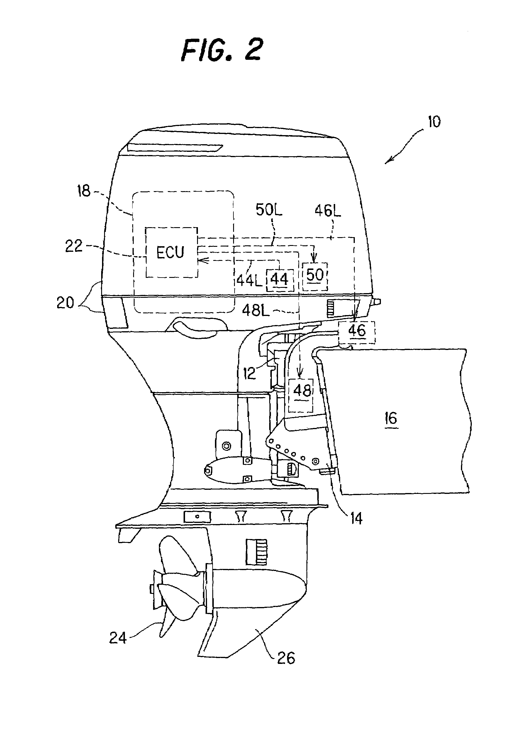
[0037]FIG. 1 is an overall schematic view of the shift mechanism for an outboard motor, and FIG. 2 is an explanatory side view of a part of FIG. 1.

[0038]Reference numeral 10 in FIGS. 1 and 2 designates an outboard motor built integrally of an internal combustion engine, propeller shaft, propeller and other components. As illustrated in FIG. 2, the outboard motor 10 is mounted on the stem of a boat (hull) 16 via a swivel case 12 (that rotatably accommodates or houses a swivel shaft (not shown)) and stem bracket 14 (to which the swivel case 12 is connected), to be rotatable about the vertical and horizontal axes.

[0039]The outboard motor 10 is equipped with an internal combustion engine 18 at its upper portion. The engine 18 is a spark-ignition, in-line four-cylinder gasoline engine with a displacement of 2,200 cc. The engine 18, located inside the outboard m...

second embodiment

[0095]FIG. 18 is a view, similar to FIG. 15, but showing a shift mechanism for outboard motors according to the invention.

[0096]In the shift mechanism according to the second embodiment, instead of the spacer 104, a spring, more precisely a coil spring 110 is inserted between the case 90 and the manually-operable grip 102. The spring 110 urges the emergency gear 100 to be lifted upwards such that the engagement with the third gear 92c in the reduction-gear mechanism 92 is disconnected. When the shifting should be carried out manually, it suffices if the operator pushes the grip 102 down to connect the emergency gear 100 to the third gear 92c.

[0097]The rest of the second embodiment as well as the advantages and effects is the same as that of the first embodiment.

[0098]As mentioned above, the first to second embodiments are configured to provide a shift mechanism for an outboard motor 10 mounted on a stern of a boat 16 and having an internal combustion engine 18 at its upper portion ...


PUM


Abstract

In a shift mechanism for an outboard motor mounted on a stem of a boat and having an internal combustion engine at its upper portion and a propeller at its lower portion that is powered by the engine to propel the boat, having an electric motor installed in the outboard motor, a shift rod rotatably connected to the electric motor, a shifter clutch connected to the shift rod, the shifter clutch being movable by the shift rod from a neutral position to engage with at least one of a forward gear and a reverse gear, and a controller controlling the electric motor to rotate the shift rod such that the shifter clutch engages with the forward gear or the reverse gear, corresponding to an inputted shift instruction made by the operator, there is provided a shock mitigator mitigating shock generated during the shift. The shock mitigator comprises projections formed on the clutch and the forward / reverse gear. Alternatively, the electric motor and its reduction-gear mechanism are accommodated in a case to be located above the shift rod. Further, there is provided an emergency gear that allows the shift rod to be rotated manually to effect shift.

Description

BACKGROUND OF THE INVENTION[0001]1. Field of the Invention[0002]This invention relates to a shift mechanism for an outboard motor.[0003]2. Description of the Related Art[0004]In outboard motor shift mechanisms, a shift is usually changed by moving a shift rod having a cam at its distal end in the longitudinal direction to slide a shift slider such that a clutch is switched from its neutral position to a forward position where it engages with a forward gear or a reverse position where it engages with a reverse gear.[0005]Alternatively, a shift rod is provided with a rod pin at a position eccentric from the rod center, in such a way that a shift slider is slid to effect shift by a distance due to a displacement of the rod pin caused by a rotation of the shift rod. The distance of travel of the rod pin corresponds to a circular arc whose radius is the amount of eccentricity of the rod pin.[0006]In the outboard motor shift mechanisms including that mentioned above, when the shift rod is...

Claims


Application Information

Patent Timeline
IPC IPC(8): B63H20/20B63H20/00B63H21/22B63H23/30F02B61/04F02B61/06
CPCB63H20/00B63H20/20B63H21/22B63H23/30F02B61/045F02B61/06
Inventor MIZUGUCHI, HIROSHITAKADA, HIDEAKIMASUBUCHI, YOSHINORIKASAI, KOJIYOSHIMURA, HAJIME
Owner HONDA MOTOR CO LTD
Learn More