Putter grip with improved vibration transmission to hands
What is Al technical title?
Al technical title is built by PatSnap Al team. It summarizes the technical point description of the patent document.
a technology of vibration transmission and grip, which is applied in the field of grip with improved vibration transmission to hands, to achieve the effect of improving impact feedback and minimizing vibration transmission
Inactive Publication Date: 2006-11-28
ROHRER TECH
View PDF5 Cites 54 Cited by
Summary
Abstract
Description
Claims
Application Information
AI Technical Summary
This helps you quickly interpret patents by identifying the three key elements:
Problems solved by technology
Method used
Benefits of technology
[0006]The present invention describes a grip for putters and other less than full swing clubs with enhanced impact vibration transmission from the club shaft to the hands via the use of rigid vibration transmitting protrusions attached to, in intimate contact with, or integral with the clubshaft and contacting the player's hands. Most embodiments allow the improved grips of the present invention to replace the conventional slip-on, or wrapped grips found on most putters and other clubs today. Some described embodiments of the present invention enhance impact vibrations in the vicinity of one or both of a player's hands on said grip via unique mounting and / or weighting of the grip and nearby shaft.
[0007]One object of the present invention is to provide a putter or other golf club grip with enhanced vibration transmission for better impact feedback between the putter shaft and the player's hands.
[0008]Another object of the present invention is to increase or amplify the impact vibrations transmitted to said grip via grip mounting and / or backweighting techniques.
[0013]Bae (U.S. Pat. No. 5,897,440) describes a grip produced by inserting numerous elastomer grommets, or “nodules” into holes in the upper end of the golf shaft with the objects of lighter weight and easier installation and replacement. The subject grip is almost the inverse of the present invention with soft energy absorbing protrusions contacting the hands vs. rigid vibration conducting protrusions.
[0018]Sears (U.S. Pat. No. 4,979,743) proposes a two cavity putter grip geometrically similar to '473 previously described, but with a single mounting point on the putter shaft at a mode of minimum impact vibration (typically 3″ to 6″ from grip top on conventionally weighted, gripped and shafted putters). The mount uses a resilient elastomer. The mounting material and mounting location minimizes vibration transmission from the shaft to the hands, the exact opposite of the present invention.
[0019]Kobayashi (U.S. Pat. No. 5,269,518), Boeckenhaupt (U.S. Pat. No. 5,465,967), Bloom (U.S. Pat. No. 6,007,431), and others, describe and claim backweighting means for putters and other clubs. Backweighting putter grips has been practiced for decades. None describe or claim backweighting such that shaft and grip vibration amplitude and transmission is maximized at one or both hands for improved impact feedback.
Problems solved by technology
It is undesirable, however, for putters and other partial swing clubs where the magnitude of impact vibrations are typically an order of magnitude less and the object is distance control not maximum distance.
Method used
Image
Click on the blue label to locate the original text in one second.
Reading with bidirectional positioning of images and text.
Examples
Embodiment Construction
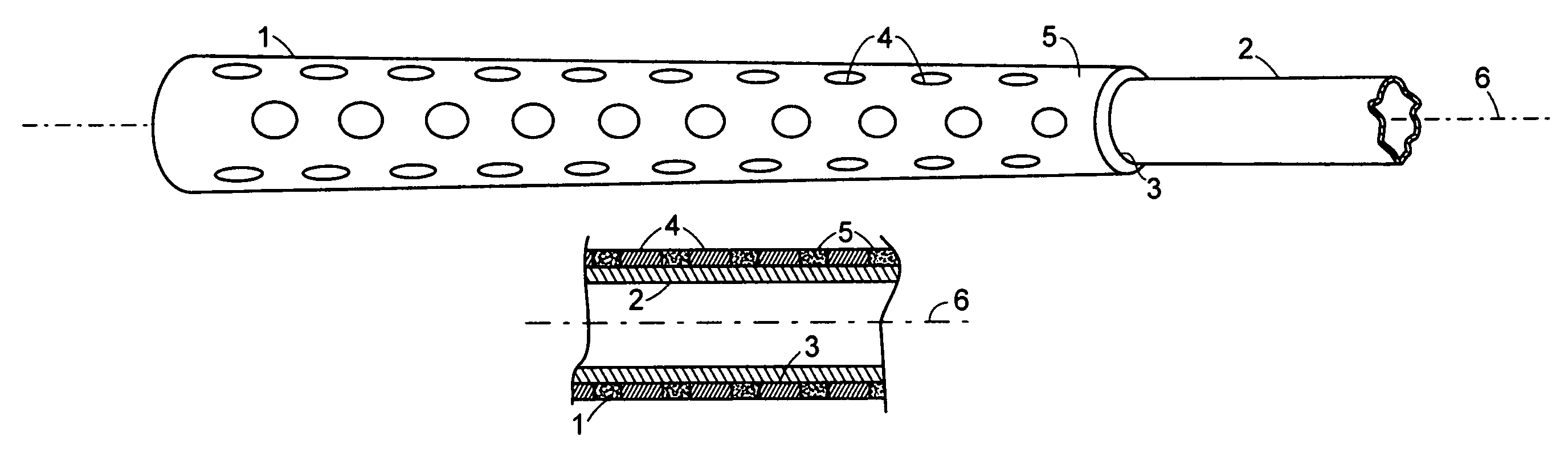
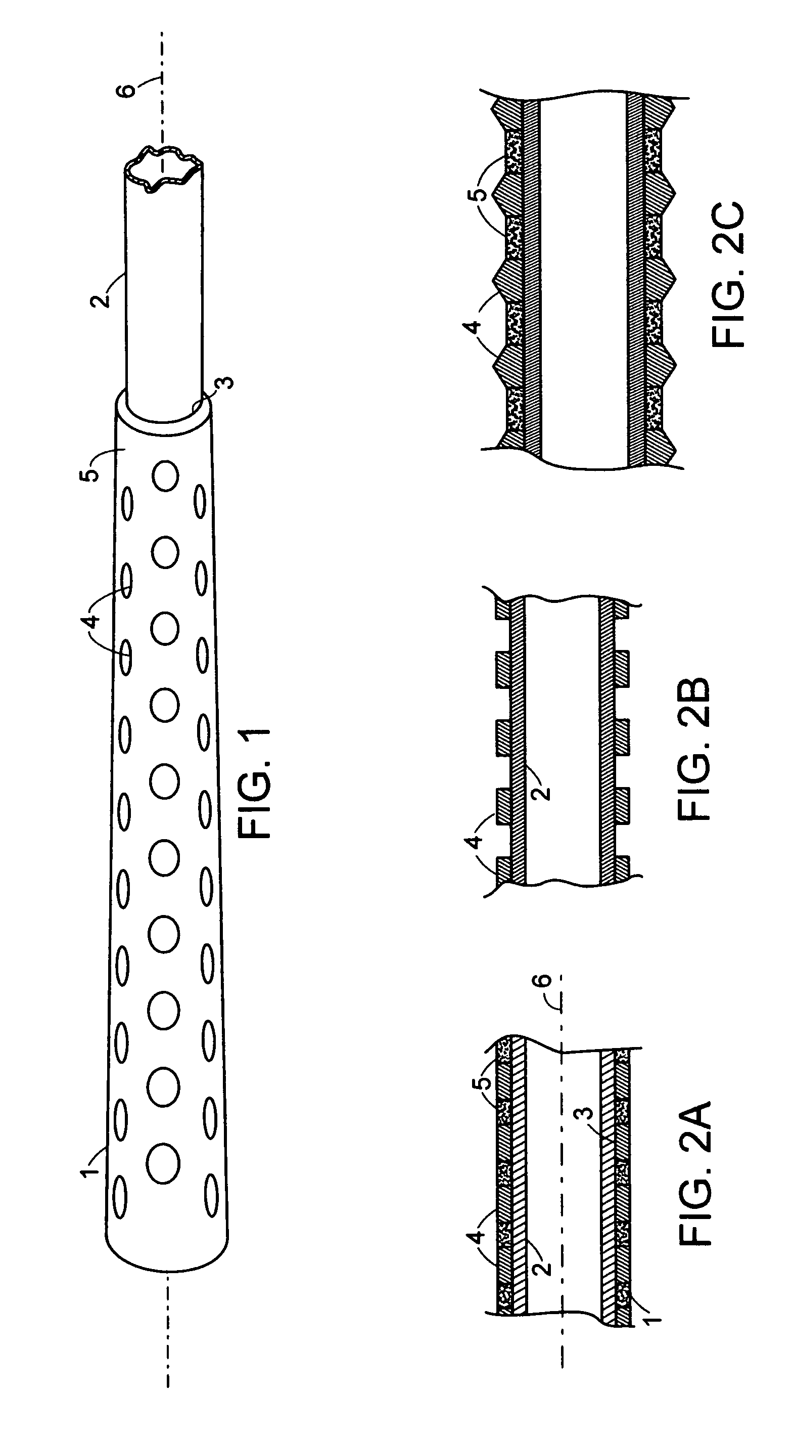
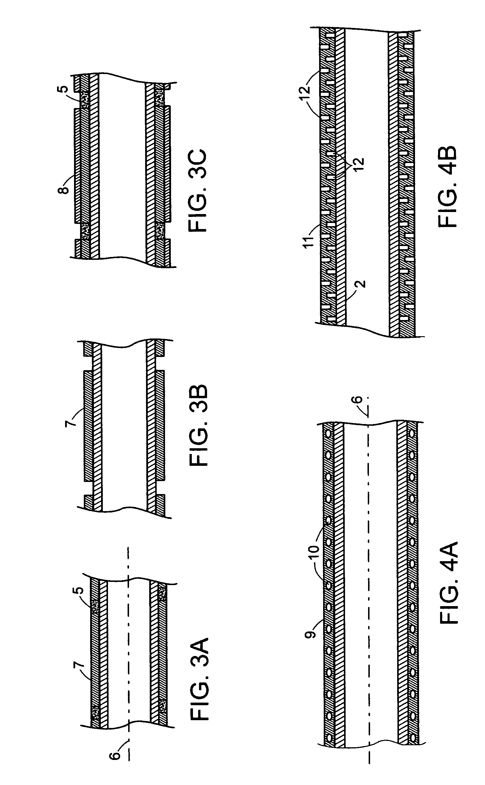
[0030]Preferred embodiments of the present invention utilize one or more metal, rigid plastic, ceramic or other vibration transmitting elements attached to, in intimate contact with, or integral with a conventional putter shaft or other club shaft at least some of said elements also contacting a player's hand or hands providing improved vibrational feedback upon clubhead impact with a ball. FIG. 1 shows a perspective view of one embodiment of a putter or other club grip 1 of the present invention, as well as, a portion of the club shaft 2 with central axis 6 on which club shaft is mounted a grip of the present invention via a thin layer of adhesive or conventional solvent activated grip tape 3 or pre-applied adhesive in the grip bore, at the juncture of said grip 1 and shaft 2, and continuing toward part or all of the length of said grip. Multiple small vibration conducting protruding elements 4 in contact with the shafts 2 or said grip mounting adhesive layer 3 protrude to or throu...
PUM
Abstract
A putter or other golf club grip has rigid vibration transmitting protrusions either attached to the club shaft or in intimate contact with both the shaft and the golfer's hands, areas between said protrusions optionally being filled with conventional grip materials. The grip may be placed over existing club shafts like conventional slip-on or wrap-on grips or become an extension thereof. The grips may be attached and weighted in such a manner to further enhance desirable impact vibrational feedback to a golfer's hands further improving a golfer's distance control while reducing off center hits and the resulting distance and directional loss.
Description
CROSS REFERENCE TO RELATED APPLICATIONS[0001]Applicant claims benefit of the filing date of Provisional Application No. 60 / 435,406, filed on Dec. 20, 2002.[0002]References CitedU.S. Patent Documents4,979,743December 1990Sears273 / 81R5,261,665November 1993Downey273 / 81B5,269,518December 1993Kobayashi273 / 81A5,465,967November 1995Beockenhaupt273 / 162R5,511,790April 1996Duran473 / 2015,575,473November 1996Turner473 / 2985,588,921December 1996Parsick473 / 2995,653,644August 1997Jaeckel473 / 3035,795,242August 1998Ree473 / 3035,897,440April 1999Bae et al.473 / 2015,964,670October 1999Cheng473 / 3195,993,327November 1999Terril473 / 2976,007,413December 1999Bloom473 / 2926,123,625September 2000Koblenz473 / 2036,251,027 B1June 2001Buchanan473 / 300Foreign Patent Document2,202,319September 1988(GB)BACKGROUND OF THE INVENTION[0003]Golf club grips have evolved over the past two centuries toward the objective of better absorption of impact shocks and vibrations. This has become especially important with the advent of st...
Claims
Application Information
Patent Timeline
Application Date:The date an application was filed.
Publication Date:The date a patent or application was officially published.
First Publication Date:The earliest publication date of a patent with the same application number.
Issue Date:Publication date of the patent grant document.
PCT Entry Date:The Entry date of PCT National Phase.
Estimated Expiry Date:The statutory expiry date of a patent right according to the Patent Law, and it is the longest term of protection that the patent right can achieve without the termination of the patent right due to other reasons(Term extension factor has been taken into account ).
Invalid Date:Actual expiry date is based on effective date or publication date of legal transaction data of invalid patent.