Portable 3D ultrasound system

a 3d ultrasound and portable technology, applied in ultrasonic/sonic/infrasonic diagnostics, instruments, applications, etc., can solve the problems of complex circuitry, machines even less portable, and machines that have not utilized recent advances in computer technology

Inactive Publication Date: 2006-11-28
KONINKLIJKE PHILIPS ELECTRONICS NV
View PDF8 Cites 101 Cited by
  • Summary
  • Abstract
  • Description
  • Claims
  • Application Information

AI Technical Summary

Problems solved by technology

These machines used transducers having a 1D array of elements, which required complicated circuitry and a complex rocking or back-and-forth movement of the transducer to generate the 3D image.
Due to their size and complexity, these machines required large power supplies and heavy power cords, which made these machines even less portable.
Furthermore, these machines have not utilized recent advances in computer technology, which allow complex signal processing to be achieved with small chip components.
Thus, previous 3D ultrasound machines were either completely stationary, moveable on a cart which weighed 300–400 pounds, or fitted into a large case which was transported in a vehicle trunk, but were too heavy to be carried by hand.
These machines were expensive to build and operate, and due to their size, ultrasound analysis could only be performed in certain locations.
Although previous portable ultrasound devices were able to generate a 2D image, the circuitry necessary to perform the beamforming, rendering and other processing necessary to generate a 3D image was too large to allow for portability.

Method used


Image

  • Portable 3D ultrasound system
  • Portable 3D ultrasound system
  • Portable 3D ultrasound system

Examples


Embodiment Construction

[0021]Reference will now be made in detail to the present preferred embodiments of the present invention, examples of which are illustrated in the accompanying drawings, wherein like reference numerals refer to like elements throughout.

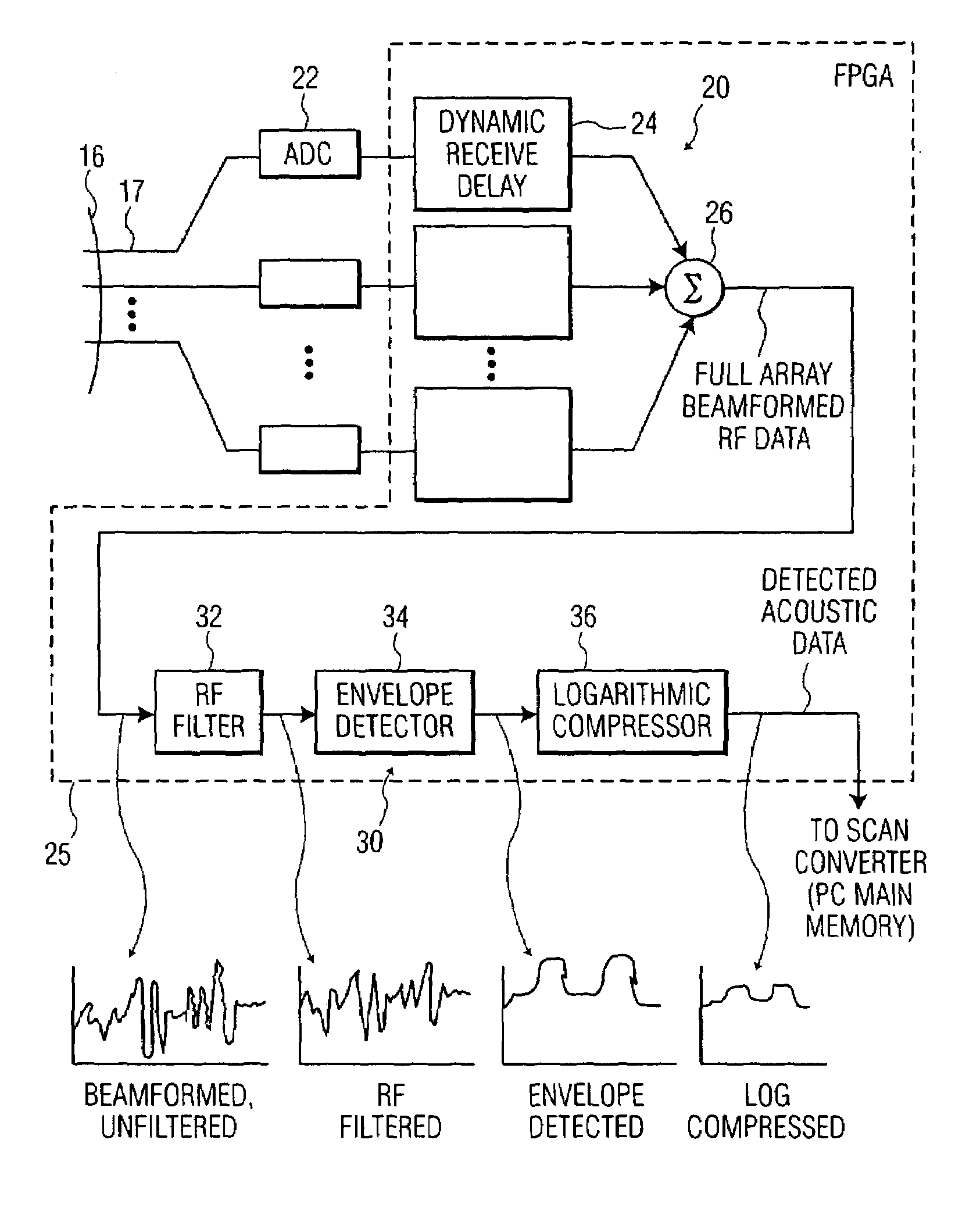
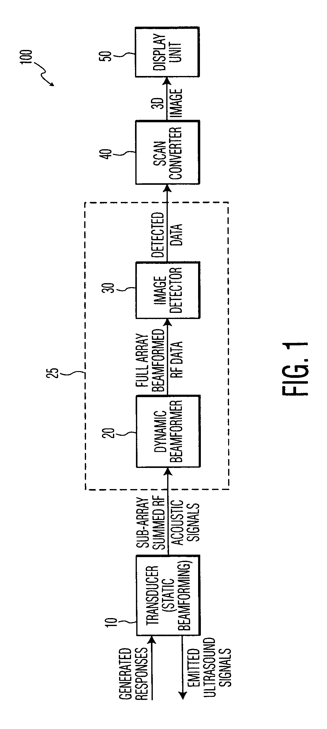
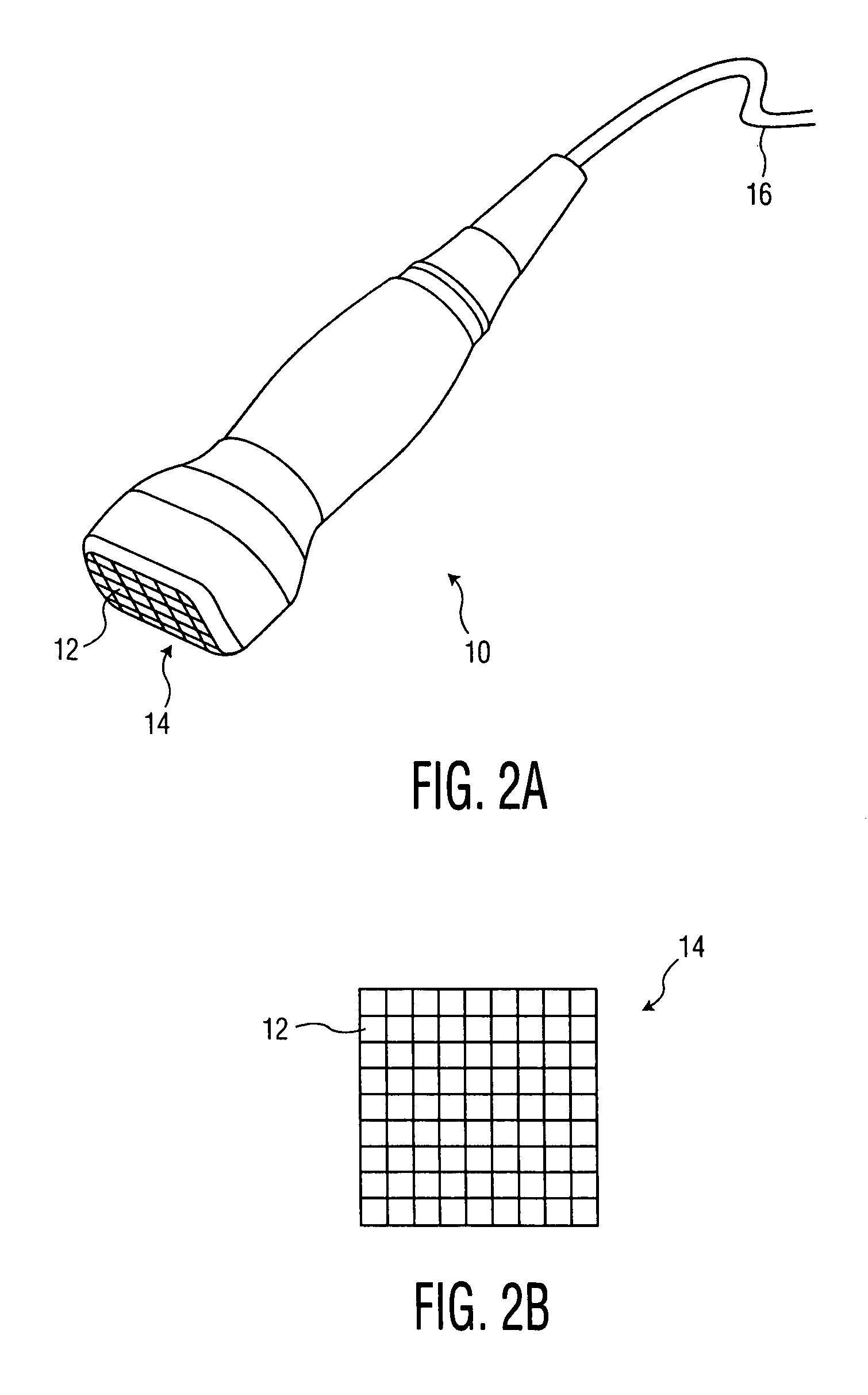
[0022]FIG. 1 is a block diagram illustrating the operation of a portable 3D ultrasound device 100 according to the present invention, which includes hand carry, hand use, or hand-held devices. A transducer 10 emits ultrasound signals which generate a response from a body (not shown) back to the transducer 10. The transducer 10 also provides static beamforming to generate a plurality of sub-array summed RF acoustic signals, which are received by a dynamic beamformer 20. The dynamic beamformer 20 performs dynamic beamforming to generate a full array of beamformed RF data, which is received by an image detector 30, which generates detected acoustic data therefrom. The dynamic beamformer 20 and the image detector 30 are formed on a PC (personal computer) ...


PUM


Abstract

A portable 3D ultrasound device having an ultrasound transducer. The ultrasound transducer includes a transducer array with a plurality of transducer elements arranged in a plurality of dimensions, the transducer array including an emitter to emit ultrasound energy, a receiver to receive responses generated in accordance with the ultrasound energy, a plurality of sub-array beamformers, a signal processor to convert the generated responses into a 3D ultrasound image and a display unit to display the 3D ultrasound image.

Description

BACKGROUND OF THE INVENTION[0001]1. Field of the Invention[0002]The present invention relates to a portable ultrasound device, and more particularly, to a hand-held or hand-carried ultrasound device that displays a 3D image.[0003]2. Description of the Related Art[0004]Previously, in order to generate a 3D ultrasound image, large machines were required. These machines used transducers having a 1D array of elements, which required complicated circuitry and a complex rocking or back-and-forth movement of the transducer to generate the 3D image. Due to their size and complexity, these machines required large power supplies and heavy power cords, which made these machines even less portable. Furthermore, these machines have not utilized recent advances in computer technology, which allow complex signal processing to be achieved with small chip components. Thus, previous 3D ultrasound machines were either completely stationary, moveable on a cart which weighed 300–400 pounds, or fitted in...

Claims


Application Information

Patent Timeline
Patent Type & Authority Patents(United States)
IPC IPC(8): A61B8/02A61B8/00G01H1/00G01H3/00G01S7/52G01S7/521G01S15/89G10K11/34
CPCG01H1/00G01H3/00G01S7/52046G01S7/52079G01S7/52082G01S15/8925G01S15/8927G01S15/8993G10K11/346A61B8/4427G01S7/5208A61B8/00
Inventor POLAND, MCKEE DWILSON, MARTHA G.
Owner KONINKLIJKE PHILIPS ELECTRONICS NV
Why Eureka
Try Eureka