Method and apparatus for removing particulate and vapor phase contaminants from a gas stream

a technology of vapor phase contaminants and gas stream, which is applied in the direction of chemistry apparatus and processes, separation processes, dispersed particle separation, etc., can solve the problems of difficult to remove volatile compounds, special design and costly emissions control systems that are required to effectively capture these trace amounts of volatile compounds, and fixed bed systems. , to achieve the effect of avoiding fly ash contamination and facilitating the disposal of collected fly ash

Inactive Publication Date: 2006-11-28
ELECTRIC POWER RES INST INC
View PDF30 Cites 88 Cited by
  • Summary
  • Abstract
  • Description
  • Claims
  • Application Information

AI Technical Summary

Benefits of technology

[0013]Accordingly, the present invention provides a method and apparatus that are capable of removing both particulate or fly ash as well as one or more vapor phase contaminants, such as mercury, from a gas stream, such as a flue gas stream generated by a coal-fired boiler. Further, the present invention provides a method and apparatus for removing fly ash and one or more vapor phase contaminants adsorbed onto an injected sorbent, wherein the fly ash is collected separately from the vapor phase contaminants adsorbed onto the sorbent, thereby avoiding contamination of the fly ash by the sorbent having the adsorbed vapor phase contaminants, which provides for easier disposal of the collected fly ash.

Problems solved by technology

Mercury is present in flue gas in very low concentrations (<1 ppb) and forms a number of volatile compounds that are difficult to remove.
Specially designed and costly emissions-control systems are required to capture these trace amounts of volatile compounds effectively.
There are, however, several disadvantages of fixed bed systems.
In addition, fixed bed systems may produce a significant pressure drop in the gas path.
These beds also require significant space and are very difficult to retrofit into existing systems such as into the ductwork of powerplants without major modifications.
However, application of heat to the porous tube while it is in the duct is not a convenient technique.

Method used


Image

  • Method and apparatus for removing particulate and vapor phase contaminants from a gas stream
  • Method and apparatus for removing particulate and vapor phase contaminants from a gas stream
  • Method and apparatus for removing particulate and vapor phase contaminants from a gas stream

Examples


Embodiment Construction

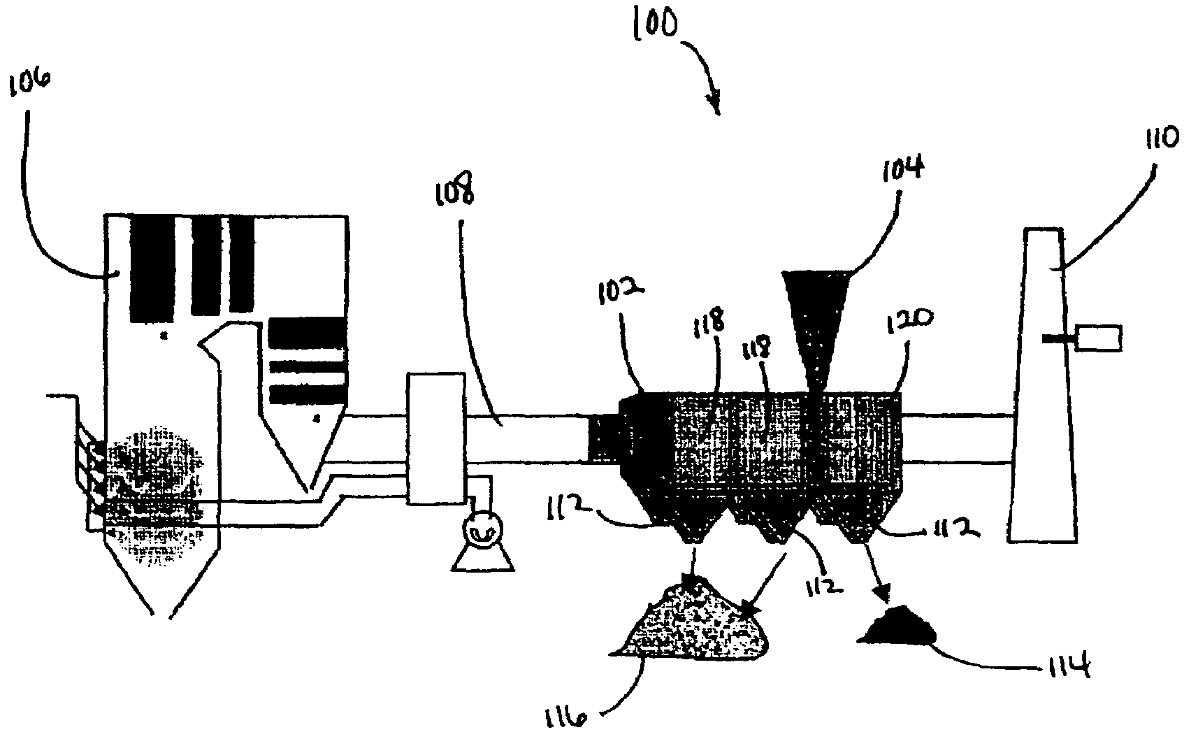
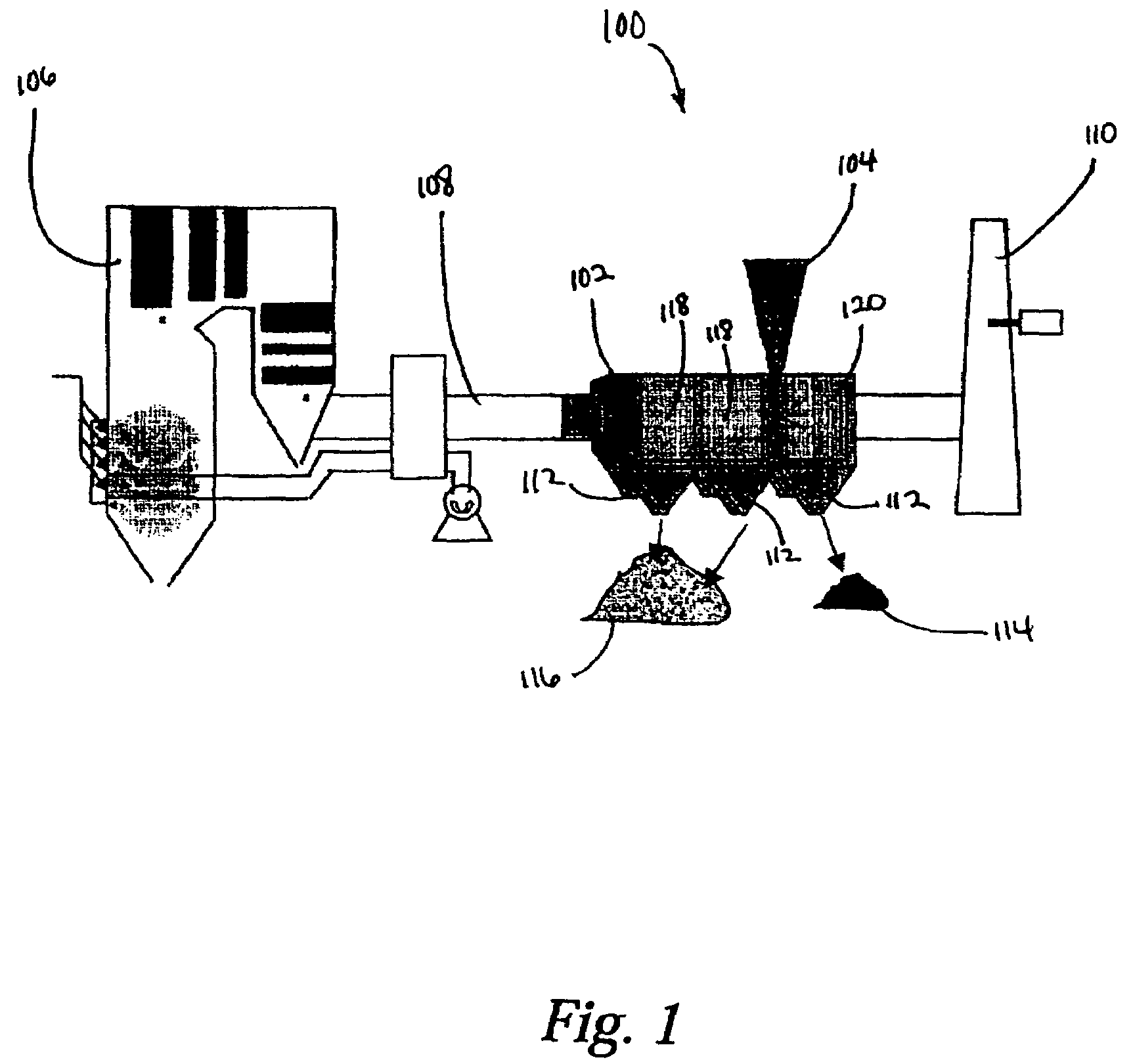
[0021]Generally, the present invention provides a method and apparatus for removing both particulate, such as fly ash, and vapor phase contaminants, such as trace metals including, for example, mercury, from a gas stream, such as flue gas stream from a coal-fired power plant. The following text in connection with the Figures describes various embodiments of the present invention. The following description, however, is not intended to limit the scope of the present invention. It should be appreciated that where the same numbers are used in different figures, these refer to the same element or structure.

[0022]FIG. 1 is a schematic diagram of one embodiment of the present invention. In the coal combustion process 100, a coal-fired boiler 106 generates a flue gas that passes through a duct 108 and is directed to a particulate collection device 102 and finally to a stack 110 where the flue gas is discharged. An injector 104 is connected to the particulate collection device 102 and is con...


PUM


Abstract

The present invention provides methods for removing particulate and a vapor phase contaminant from a gas stream including, in one embodiment, directing a gas stream comprising fly ash and a vapor phase contaminant into a particulate collection device, wherein the particulate collection device includes an upstream collection section and a downstream collection section; removing at least a portion of the fly ash from the gas stream in the upstream collection section; injecting a sorbent into the particulate control device between the upstream collection section and the downstream collection section; adsorbing the vapor phase contaminant onto the sorbent to produce spent sorbent; and removing the spent sorbent from the gas stream in the upstream collection section. An apparatus is also provided for performing the methods.

Description

BACKGROUND OF THE INVENTION[0001]1. Field of the Invention[0002]The present invention relates generally to the removal of particulate and vapor phase contaminants from a gas stream. More specifically, the present invention relates to the removal of particulates, such as fly ash and vapor phase contaminants, such as mercury, from a gas stream, such as a flue gas stream from a coal-fired boiler.[0003]2. Description of Related Art[0004]Utility power plants, in particular, coal-fired power plants, remove particulate matter, such as fly ash, from flue gas generated by the boiler before releasing the flue gas to the atmosphere. Typical methods for removing fly ash include the use of an electrostatic precipitator or baghouse filter. The collected fly ash must then be properly disposed of, taking into account its composition.[0005]Utility power plants also are concerned about emission of trace metals in light of the 1990 Clean Air Act Amendment (CAAA) on air toxics (Title III). Special atte...

Claims


Application Information

Patent Timeline
Patent Type & Authority Patents(United States)
IPC IPC(8): B03C3/017B03C3/013B03C3/02
CPCB03C3/013B03C3/017B03C3/025
Inventor CHANG, RAMSAY
Owner ELECTRIC POWER RES INST INC
Why Eureka
Try Eureka