Glass panel
a glass plate and glass plate technology, applied in the field of glass panels, can solve the problems of easy damage to glass plates b>1/b> per se, inability to maintain decompression void v, etc., and achieve the effects of reducing excellent heat insulation performance, and restrainting the risk of glass damag
- Summary
- Abstract
- Description
- Claims
- Application Information
AI Technical Summary
Benefits of technology
Problems solved by technology
Method used
Image
Examples
first embodiment
[0060][First Embodiment]
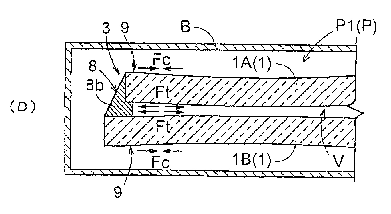
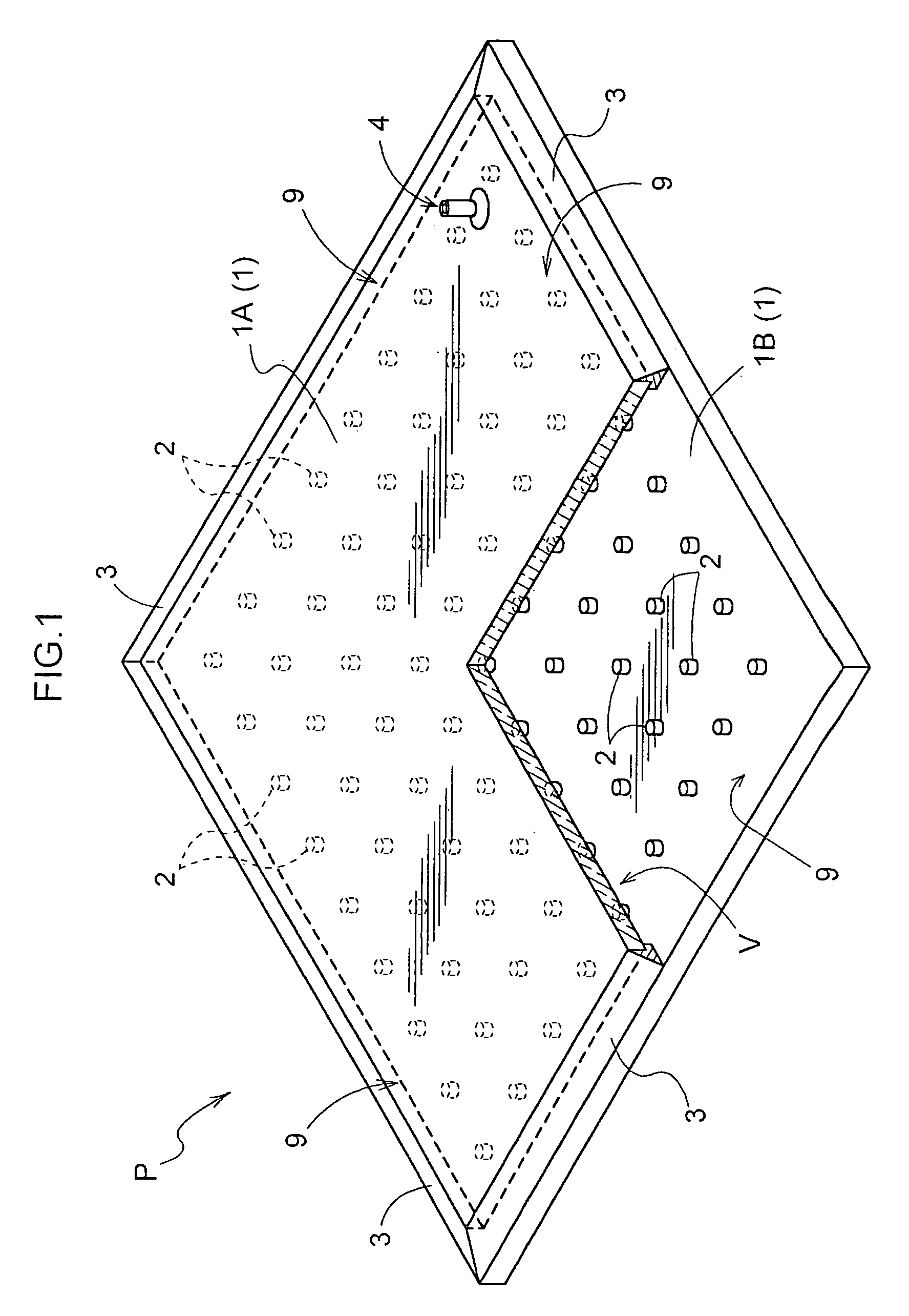
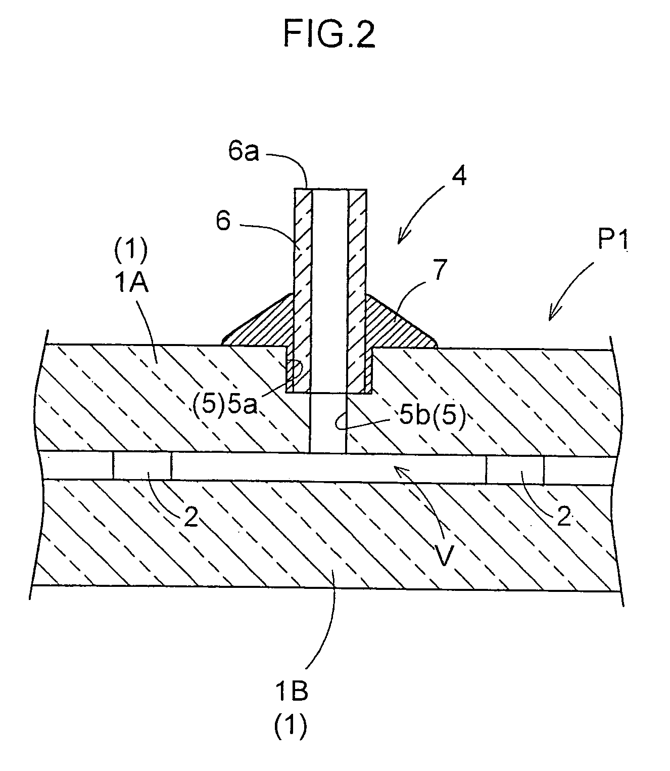
[0061]FIG. 1 shows a glass panel P in one embodiment of the present invention. The glass panel P comprises a pair of glass plates I (1A, 1B) opposed to each other, a plurality of spacers2 disposed between the glass plates and spaced from each other along plate surfaces for maintaining a gap between the glass plates, and low melting point glass 3 such as solder glass of low gas permeability acting as a sealing member having a lower melting point than the glass plates 1 for sealing the glass plates 1 along the entire circumference at outer peripheries 9 thereof to define a decompression void V between the pair of glass plates 1A and 113. At outer surfaces of the outer peripheries 9 adjacent where the glass plates 1A and 1B are sealed to each other through the low melting point glass (sealing member) 3 remains a compressive force Fc of approximately 0.5 to 4.0 MPa with the decompression void V being under at normal pressure (atmospheric pressure).
[0062]The glass...
second embodiment
[0081][Second Embodiment)
[0082]It is possible to modify the glass panel P having the compression force Fe remaining at the outer surface of the outer peripheries of each glass plate 1A or 1B adjacent where the glass plates are sealed by the low melting point glass (sealing member) 3 with the decompression void V at atmospheric pressure. As illustrated in FIG. 6, the glass plates IA and 1B of the glass panel P may be arranged parallel or substantially parallel to each other across the decompression void V to be sealed with each other at the outer peripheries 9 thereof through the low melting point glass (sealing member) 3, allowing the compressive force Fe to remain at the outer surfaces of the outer peripheries 9 adjacent the sealed portions. To this end, it is effective to maintain the pair of glass plates IA and 1B in parallel by clipping the outer peripheries 9 of the plates at appropriate intervals, or to place a plate-like weight on the surface of the upper glass plate 1.A.
[008...
embodiment 1
[0086][Alternative Embodiment 1]
[0087]In forming the glass panel P by arranging the pair of glass plates I cut by a cutter to be opposed to each other, the directions of cut portions have not been determined in use since this does not significantly affect the properties, e.g. a thermal insulation performance, of the glass panel P.
[0088]When the glass plates 1 are subjected to a load from the outside such as a wind pressure or impact, a bending moment acts on the glass plates 1. However, since the glass plates 1 are rigidly joined to each other at the outer peripheries 9 thereof by the sealing member, the two glass plates 1A and 1B combine to cope with the load as if a single glass plate. Therefore, a tensile stress occurs on the outer surfaces at the outer peripheries exposed to the atmosphere of one of the glass plates 1A, while a compressive stress occurs on the outer surfaces at the outer peripheries exposed to the atmosphere of the other glass plate 1B. In addition, a stress neu...
PUM
| Property | Measurement | Unit |
|---|---|---|
| pressure | aaaaa | aaaaa |
| height | aaaaa | aaaaa |
| melting point | aaaaa | aaaaa |
Abstract
Description
Claims
Application Information
 - R&D
- Intellectual Property
- Life Sciences
- Materials
- Tech Scout
- Unparalleled Data Quality
- Higher Quality Content
- 60% Fewer Hallucinations
Browse by: Latest US Patents, China's latest patents, Technical Efficacy Thesaurus, Application Domain, Technology Topic, Popular Technical Reports.
© 2025 PatSnap. All rights reserved.Legal|Privacy policy|Modern Slavery Act Transparency Statement|Sitemap|About US| Contact US: help@patsnap.com


