
Method and control device for determining the position of a local coil on a patient table of a magnetic resonance scanner

a technology of magnetic resonance scanner and local coil, which is applied in the direction of instruments, diagnostic recording/measuring, and using reradiation, can solve the problem of not being able to move the patient table continuously, and achieve the effect of safe and precise localization

Inactive Publication Date: 2006-11-28
SIEMENS HEALTHCARE GMBH
View PDF8 Cites 17 Cited by
  • Summary
  • Abstract
  • Description
  • Claims
  • Application Information

AI Technical Summary

Benefits of technology

[0009]It is an object of the present invention to improve a method of the initially cited type for automatic detection of the position of a local coil, so that the local coil can be relatively safely and precisely localized independent of its position on the patient table, and in particular so that the aforementioned problems are prevented. Moreover, it is an object of the invention to provide a corresponding control device and a magnetic resonance tomograph apparatus with which such a measurement can be implemented.
[0012]By the shifting of the patient table in or between the measurements, the measurable signal profile is virtually [sic] moved through the magnetic resonance system. If the local coil is located within the scanner, the signal profile shifts approximately with the movement of the patient table. The signal profile varies in an unpredictable manner at the edge of the scanner and a relevant signal profile is no longer measured outside of the scanner. Only the change or shift of the signal profile then has to be protocolled and compared with the shift of the position of the patient table relative to the scanner. The region in which a reliable signal profile is registered then can be very simply identified from these data. These are precisely the regions in which the shift of the signal profile corresponds to the shift of the patient table relative to the scanner. In this manner, it can be easily identified when a local coil is located within the scanner. The position of the local coil relative to the patient table can then be positively determined.
[0013]Further advantages of the inventive method are that, by the consideration of a number of signal profiles for an individual position determination—which is different than the use of only one stationary exposure of a coil profile—the noise of individual measurements and the distortion can be excluded by averaging over the various measurements or by symmetry considerations, and thus the position determination is possible with far higher precision than with conventional techniques.
[0015]Preferably, only a characteristic position value representing the appertaining signal profile is determined from the measured signal profiles, for example a maximum or a primary focus of the signal profile. For this, the evaluation device preferably has a suitable profile analysis unit. The position of the local coil is then determined based on these scalar position values and not by the use of the complete signal profiles. This significantly accelerates and simplifies the calculation of the position.

Problems solved by technology

In principle, however, it is also sufficient—for example with systems that, dependent on hardware, are not able to move the patient table continuously through the scanner—to move the patient table to a number of discrete positions within the scanner and there to implement individual measurements of the signal profiles, which are then evaluated further.

Method used


Image

  • Method and control device for determining the position of a local coil on a patient table of a magnetic resonance scanner
  • Method and control device for determining the position of a local coil on a patient table of a magnetic resonance scanner
  • Method and control device for determining the position of a local coil on a patient table of a magnetic resonance scanner

Examples


Embodiment Construction

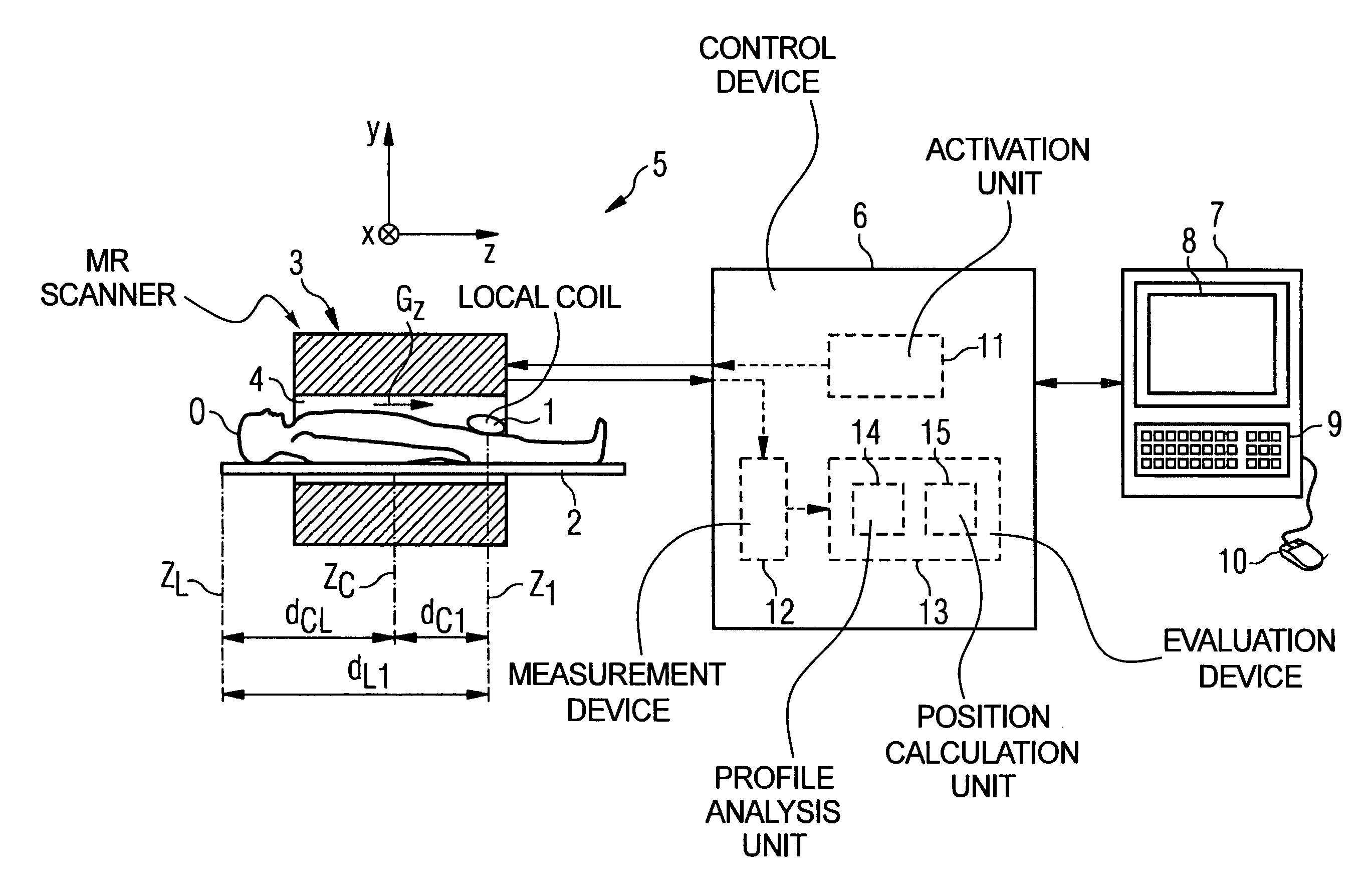
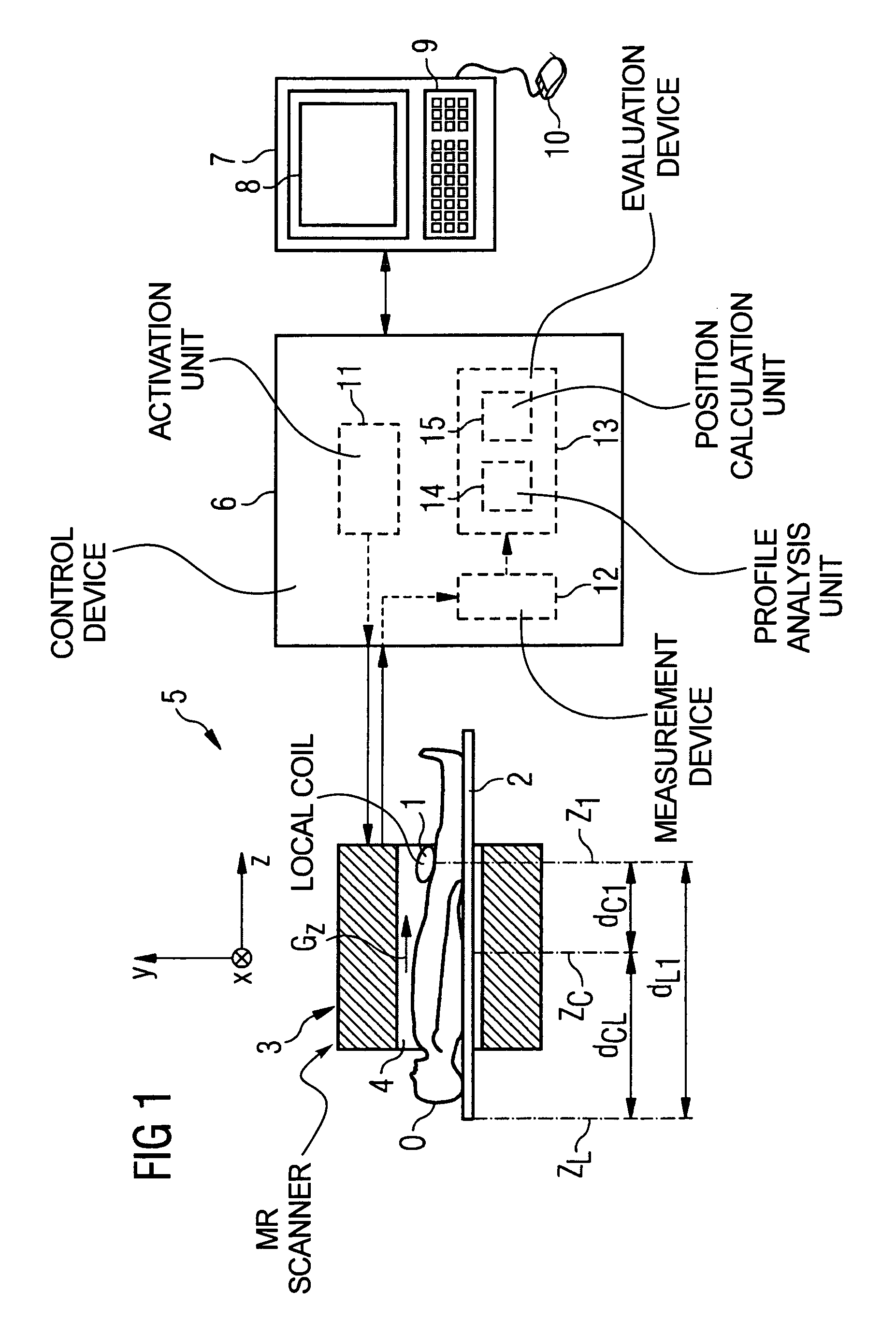
[0027]FIG. 1 shows an exemplary embodiment for a magnetic resonance system 5 in which an automatic determination of the position of a local coil 1 is possible according to the inventive method. The core of this magnetic resonance system 5 is a scanner 3 itself, in which a patient O is positioned on the patient table 2 in an annular basic field magnet (not shown in detail) that surrounds the measurement space 4.

[0028]The patient table 2 can be shifted in the longitudinal direction, i.e. along the longitudinal axis of the scanner 3. This direction is designated as the z-direction in the spatial coordinate system (likewise shown). A whole-body coil with which radio-frequency pulses can be emitted and received is located within the basic field magnet in the scanner 3. Moreover, in a typical manner the scanner 3 has gradient coils in order to be able to apply a magnetic field gradient in each of the spatial directions x, y, z.

[0029]The scanner 3 is operated by a control device 6 that is ...


PUM


Abstract

In a method and control device for determining the position in at least one spatial direction of a local coil on a patient table in a scanner of a magnetic resonance tomography apparatus, a radio-frequency signal is emitted in the presence of a magnetic field gradient applied in the appertaining spatial direction and a signal profile is measured by the local coil along the magnetic field gradient. The signal profile is acquired for each of a number of positions of the patient table relative to the scanner along the magnetic field gradient. Based on the measured signal profile the position of the local coil is determined.

Description

BACKGROUND OF THE INVENTION[0001]1. Field of the Invention[0002]The present invention concerns a method for determining the position in at least one spatial direction of a local coil on a patient positioning table or board within a magnetic resonance tomography scanner, in which a radio-frequency signal is emitted in volume in which a magnetic field gradient is applied in the appertaining spatial direction and a signal profile is measured along the magnetic field gradient by means of the appertaining local coil. The invention also concerns a corresponding control device for a magnetic resonance tomography apparatus for determining the position of a local coil according to such a method as well as a magnetic resonance tomography apparatus with such a control device.[0003]2. Description of the Prior Art[0004]Modern magnetic resonance examination systems normally operate with a number of various antennas (called coils in the following) to emit radio-frequency pulses for nuclear magneti...

Claims


Application Information

Patent Timeline
Patent Type & Authority Patents(United States)
IPC IPC(8): G01V3/00A61B5/055G01R33/341G01R33/3415
CPCG01R33/3415
Inventor CAMPAGNA, SWEN
Owner SIEMENS HEALTHCARE GMBH
Learn More