DMA controller having a trace buffer

a dma controller and buffer technology, applied in the field of dma controllers, can solve the problems of difficult to determine whether or not the allocation of dma request sources is appropriate on the system level, and the difficulty of extracting only traced at the associated dma controller, so as to facilitate the effect of facilitating the debugging of any program

Inactive Publication Date: 2006-11-28
RENESAS ELECTRONICS CORP
View PDF12 Cites 29 Cited by
  • Summary
  • Abstract
  • Description
  • Claims
  • Application Information

AI Technical Summary

Benefits of technology

[0008]The present invention is proposed to solve the above-mentioned problems, and it is therefore an object of the present invention to provide a DMA controller that enables extraction of trace data only associated with the DMA controller, and that, by enabling trace of information on each channel of the DMA controller, can strongly support debugging on the system level, and a semiconductor integrated circuit containing the DMA controller.
[0009]In accordance with an aspect of the present invention, there is provided a DMA controller including: an arbitration unit for arbitrating among a plurality of channels so as to select a DMA request from among a plurality of DMA requests accepted by way of the plurality of channels according to priorities assigned to the plurality of channels in advance; and a trace buffer for storing trace data associated with the DMA request selected by the arbitration unit. Accordingly, the DMA controller makes it possible to easily determine if DMA transfers that are not to be intended have been activated, if the assignment of the priorities to the plurality of channels is appropriate, if wrong addressing has been done, and if DMA transfers have been carried out properly, thus facilitating the debugging of any program.
[0010]In accordance with anoth

Problems solved by technology

A problem with a prior art trace method implemented as above is that though it is possible to perform a control operation so that trace data includes no data associated with CPU accesses, the trace data generally includes data associated with transfers by other bus masters and only data associated with an address bus can

Method used


Image

  • DMA controller having a trace buffer
  • DMA controller having a trace buffer
  • DMA controller having a trace buffer

Examples


embodiment 1

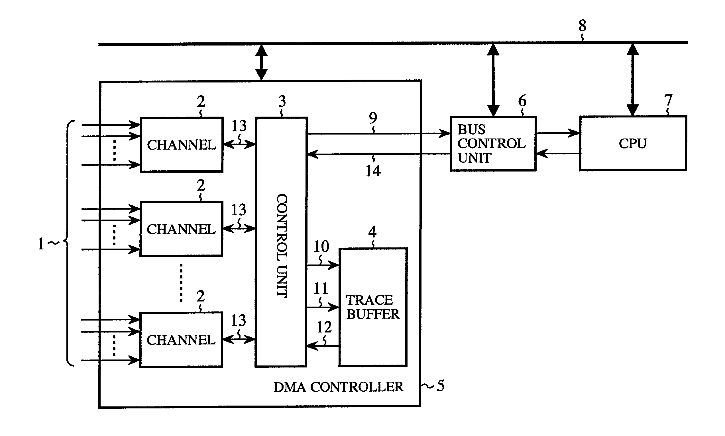
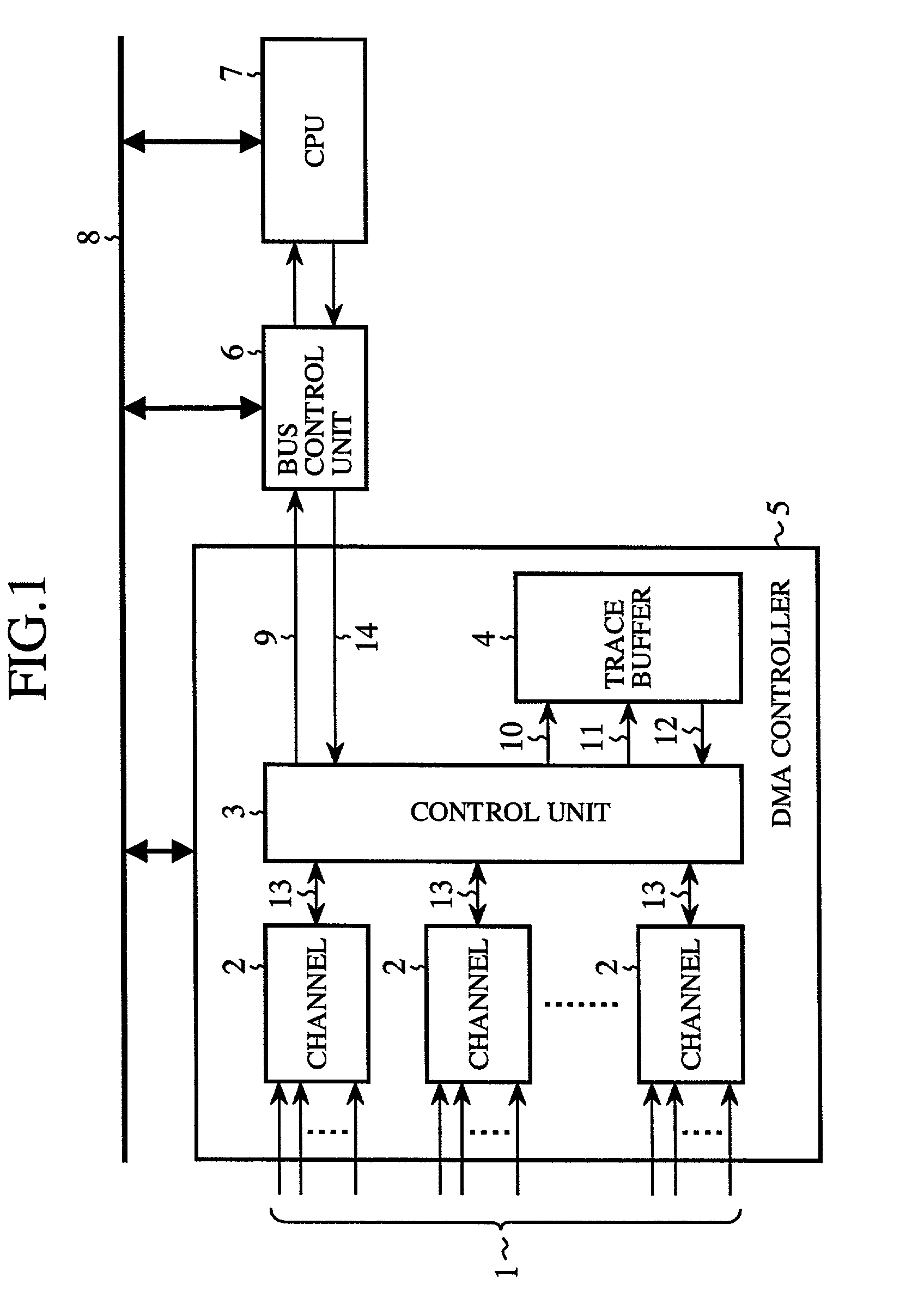
[0032]Referring now to FIG. 1, there is illustrated a block diagram showing the structure of a DMA controller according to a first embodiment of the present invention and a semiconductor integrated circuit including the DMA controller. In the figure, reference numeral 1 denote DMA request signals applied to the DMA controller 5, reference numeral 2 denotes a channel of the DMA controller 5, reference numeral 3 denotes a control unit that controls the DMA controller 5, and that also serves as an I / O interface between the DMA controller 5 and a bus 8, reference numeral 4 denotes a trace buffer, reference numeral 6 denotes a bus control unit connected to the control unit 3 of the DMA controller 5, for arbitrating among a functional module 7, such as a CPU, connected to the bus 8, the DMA controller 5, etc. for the right to use the bus 8, reference numeral 9 denotes a control signal transmitted from the DMA controller 5 to the bus control unit 6, reference numeral 14 denotes a DMA trans...

embodiment 2

[0055]FIG. 10 is a block diagram showing the structure of a DMA controller according to a second embodiment of the present invention and a semiconductor integrated circuit containing the DMA controller. The DMA controller 5 according to the second embodiment has a write control function for enabling or disabling writing of trace data 11 in a trace buffer 4, in addition to the same structure as that of the DMA controller according to the above-mentioned first embodiment as shown in FIG. 1.

[0056]In FIG. 10, the same reference numerals as shown in FIG. 1 denote the same components as those of the DMA controller 5 according to the above-mentioned first embodiment, and therefore the explanation of those components will be omitted hereafter. In FIG. 10, reference numeral 47 denotes a register connected to a bus 8, in which the value of a first trace control signal 48 applied thereto by way of the bus 8 is written, for enabling or disabling writing of trace data in the trace buffer 4, refe...

embodiment 3

[0064]FIG. 11 is a block diagram showing the structure of a DMA controller according to a third embodiment of the present invention and a semiconductor integrated circuit containing the DMA controller. The DMA controller 5 according to the third embodiment of the present invention has a function of setting trigger conditions each for triggering writing of trace data in a trace buffer 4 and selecting one of the trigger conditions, in addition to the structure of that according to the above-mentioned first embodiment as shown in FIG. 1.

[0065]In FIG. 11, the same reference numerals as shown in FIG. 1 denote the same components as those of the DMZA controller 5 according to the above-mentioned first embodiment, and therefore the explanation of those components will be omitted hereafter. In FIG. 11, reference numeral 60 denotes a trigger condition selection register in which a value to select one trigger condition from among a plurality of trigger conditions is stored, for outputting a t...


PUM


Abstract

A DMA controller comprises an arbitration unit for arbitrating among a plurality of channels so as to select a DMA request from among a plurality of DMA requests accepted by way of the plurality of channels according to priorities assigned to the plurality of channels in advance, and a trace buffer for storing trace data associated with the DMA request selected by the arbitration unit. The DMA controller can also include a write control unit for enabling or disabling writing of the trace data associated with the DMA request selected by the arbitration unit in the trace buffer.

Description

BACKGROUND OF THE INVENTION[0001]1. Field of the Invention[0002]The present invention relates to a DMA controller provided with a trace buffer for storing trace data to assist the debugging of a program or a system, in a semiconductor integrated circuit equipped with a functional module such as a CPU, and a semiconductor integrated circuit provided with the DMA controller.[0003]2. Description of the Prior Art[0004]Conventionally, in a semiconductor integrated circuit provided with a functional module, such as CPU, and a DMA controller, to assist the debugging of a program or a system, a method of tracing addresses and data transmitted by way of a bus connected to both the functional module and the DMA controller is used.[0005]Referring now to FIG. 20, there is illustrated a block diagram showing the structure of terminal equipment and a data collector which implements an example of such a prior art trace method as disclosed in Japanese patent application publication (TOKKAIHEI) No. ...

Claims


Application Information

Patent Timeline
IPC IPC(8): G06F13/28G06F11/34G06F11/28G06F13/30
CPCG06F13/30Y02B60/1228Y02D10/00
Inventor SAKUGAWA, MAMORU
Owner RENESAS ELECTRONICS CORP
Why Eureka
Try Eureka