Apparatus and methods relating to image coding

a technology of image coding and apparatus, applied in the field of pattern recognition and detection, can solve the problems of reducing the overall dynamic range of images, limiting the use of halftone information in cells, and reducing the spatial extent of halftone information, so as to achieve more flexibility and high density

Inactive Publication Date: 2006-12-05
ANOTO AB
View PDF33 Cites 16 Cited by
  • Summary
  • Abstract
  • Description
  • Claims
  • Application Information

AI Technical Summary

Benefits of technology

[0014]A specific advantage of the invention is that, by printing an image using a coding pattern containing further information which enables interaction, it allows for more flexibility when providing products with images. More space can be appointed to images as compared to traditional presentations where barcodes, tick-boxes etc. are used. Moreover, it is advantageous that the printing of the image and the coding pattern is performed in one and the same step.
[0015]Needless to say, a product according to the invention can be made more aesthetically pleasing to view in that the image itself comprises the regions allowing the interaction.
[0016]A general advantage of pattern and pattern production according to the aspects of the invention is more or less related to the fact that this is a digital operation. The positions of the markings are entered and interpreted as binary numbers, in which case the equipment to be used can be of relatively simple nature.
[0017]According to the aspects of the invention pattern and pattern production may be more or less related to the fact that this may be a digital operation. The positions of the markings may be entered and interpreted as binary numbers, in which case the equipment to be used can be of relatively simple nature.
[0018]A more or less problematic situation which can arise in the printing of markings, i.e. screen-printing points, with varying spatial extents may be of course that the markings can overlap one another in certain areas. These areas may be characterized by a relatively high density. Such overlaps may make it more difficult to determine the location of single markings and thus make it more difficult to read the additional information coded in the markings. Certainly, the problem can be avoided by markings that can be expected to overlap being limited in their spatial extents even before the printing. However, this entails limiting the dynamic range with respect to the density variation that characterizes the image printed with the coding pattern.
[0019]Known solutions with respect to the determination of the locations of overlapping markings can be drawn from, for example, the technique of astrometrically determining positions of imaged stars that are located in dense star fields. This technique tells us that with knowledge gathered in advance about the appearance, in the form of intensity distribution within the markings, of single markings, the positions of the markings, i.e. the positions of the stars, can be determined even if a plurality of the markings overlap one another. Three-dimensional pattern recognition algorithms are applied that more or less directly give, for example, the center point of a marking that “flows together” with adjoining markings.

Problems solved by technology

A drawback of the invention presented in U.S. Pat. No. 5,315,098 is that its use is restricted to applications where the halftone cells are of constant spatial extension across an image.
Another restriction is that the halftone information in the cells is restricted in spatial extent in that it must have an elongated shape.
This means that each halftone cell must contain an empty area thus reducing the overall dynamic range of the image.
Such overlaps may make it more difficult to determine the location of single markings and thus make it more difficult to read the additional information coded in the markings.
However, this entails limiting the dynamic range with respect to the density variation that characterizes the image printed with the coding pattern.
A disadvantage of astrometrical techniques is that they presuppose advance knowledge of the three-dimensional appearance of the markings and their intensity distribution.
Certainly, these contrasting indicators can be of more or less arbitrary configuration but it certainly suggests itself to utilize simple symbols such as points, circles or rectangles since reading and interpreting such symbols may require a limited set of image analysis operations to detect them.

Method used


Image

  • Apparatus and methods relating to image coding
  • Apparatus and methods relating to image coding
  • Apparatus and methods relating to image coding

Examples


Embodiment Construction

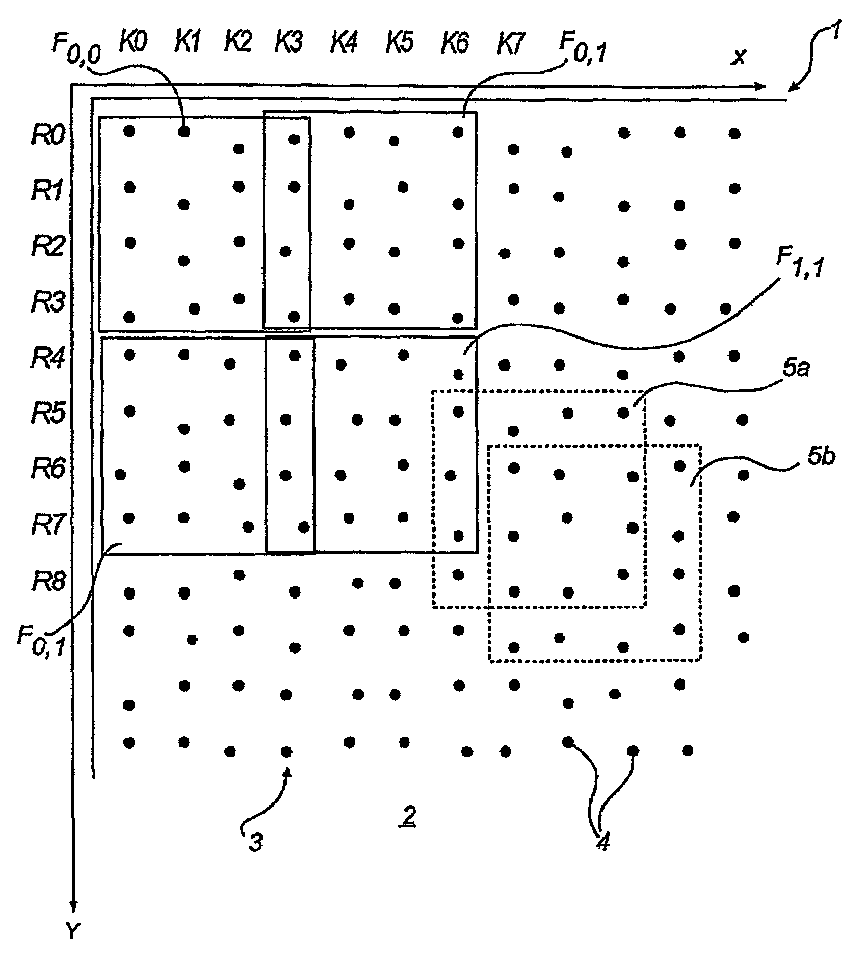
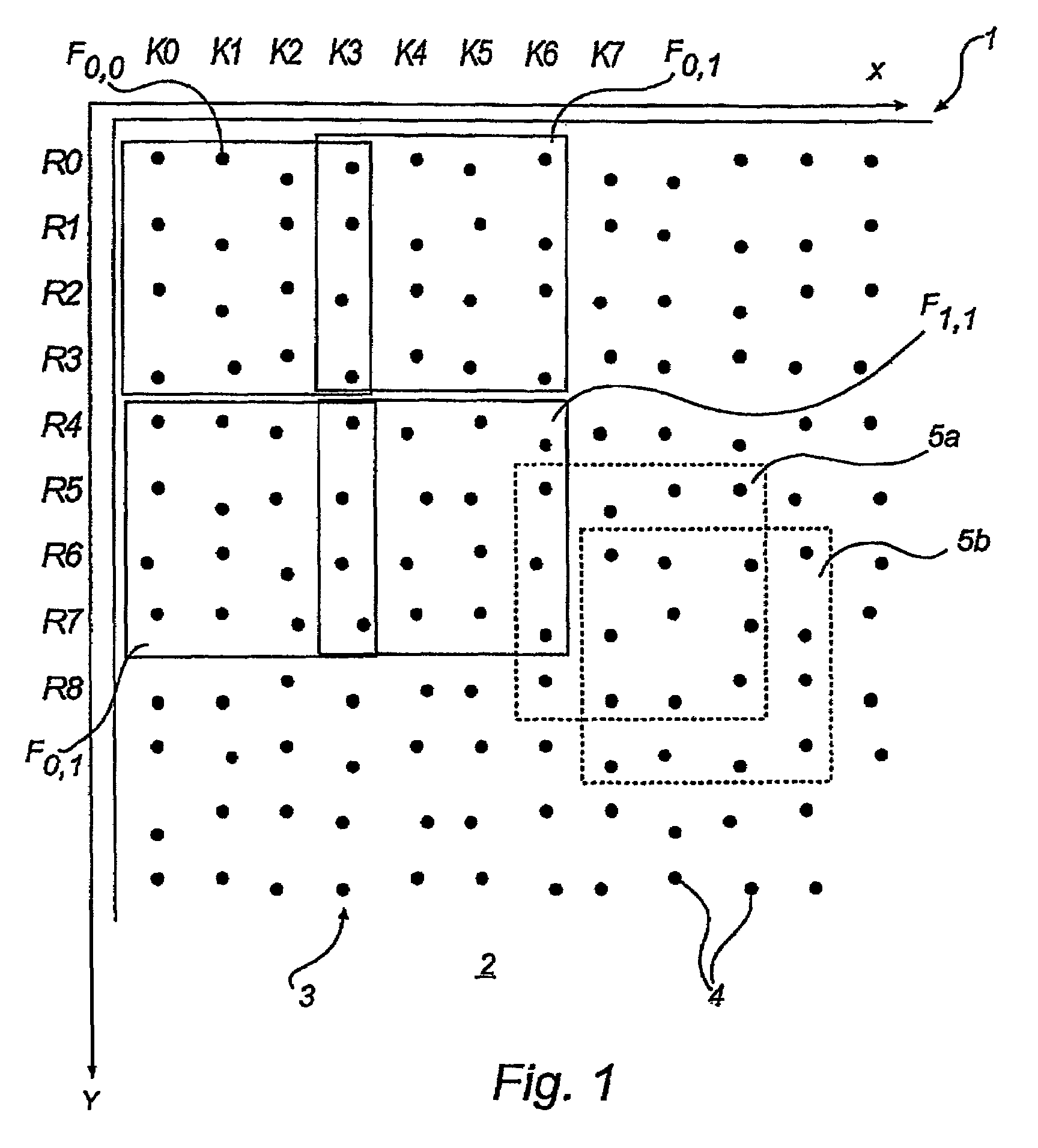
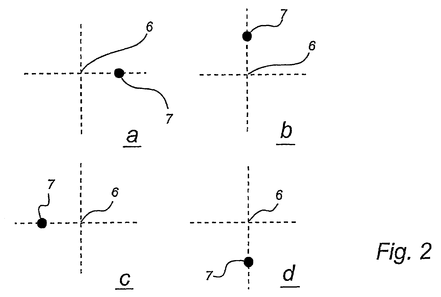
[0036]For the sake of clarity, the detailed description of the invention below may be divided into a number of part-descriptions. As an introduction, a coding pattern will be presented with reference to FIGS. 1, 2a–d and 3. This coding pattern can be used for information storage as has been outlined above. As an example, the information stored in the pattern may include position information. After the presentation of the coding pattern, an apparatus intended for reading the pattern is then presented in connection with FIG. 4. After that is shown how an image can be produced by printing a screen pattern in the form of the coding pattern presented, comprising markings of varying extents, referring to FIGS. 5a and 5b. Finally, a method of modifying the appearance of the pattern markings that, on printing an image, overlap one another, is presented with reference to FIGS. 6a and 6b.

[0037]In the following discussion regarding the coding pattern a number of calculations take place. These...


PUM


Abstract

A product has a coding pattern on its surface. The coding pattern may include symbols representing at least two different values and where each symbol comprises a raster point and at least one marking. The raster point is included in a raster that extends over the surface and the value of each symbol is indicated by the placement of the marking in relation to the raster point. The markings may each have a spatial extent that, in combination, may at least partially form the image.

Description

CROSS-REFERENCE TO RELATED APPLICATIONS[0001]This application claims priority benefits based on Swedish Patent Application No. 0000950-6, filed Mar. 21, 2000, and U.S. Provisional Application 60 / 207,838, filed Mar. 30, 2000, the technical disclosures of each of which are hereby incorporated herein by reference.FIELD OF THE INVENTION[0002]The present invention relates to pattern recognition and detection. Specifically, the present invention relates to methods and apparatuses for reading information from images stored as a pattern on a surface.BACKGROUND OF THE INVENTION[0003]In many contexts, both commercial and scientific, it is important to create an image on a surface, where the image contains as much information as possible. In this context, images can comprise, for example, photographically produced images of real objects and artificially generated images where information is represented by structures of varying blackness. In addition to the information, which is directly visibl...

Claims


Application Information

Patent Timeline
Patent Type & Authority Patents(United States)
IPC IPC(8): G06K7/10G06F3/03G06F3/033
CPCG06F3/0317G06F3/03542G06K9/22G06K19/06046G06K2009/226G06F3/0321G06V10/17G06V10/19
Inventor ERICSON, PETTER
Owner ANOTO AB
Why Eureka
Try Eureka