Rotary atomizer and coating method by it

a technology of rotary atomizer and coating method, which is applied in the direction of electrostatic spraying apparatus, burners, coatings, etc., can solve the problem that the diameter of the spray pattern cannot be smaller than a certain valu

Inactive Publication Date: 2006-12-05
TOYOTA JIDOSHA KK +1
View PDF10 Cites 70 Cited by
  • Summary
  • Abstract
  • Description
  • Claims
  • Application Information

AI Technical Summary

Benefits of technology

[0010]An object of the present invention is to provide a bell-type rotary atomizer which can achieve a diametrically small spray pattern for coating such parts as described above and can switch its spray pattern into either diametrically large or small one at any time.

Problems solved by technology

However, the diameter of the spray pattern cannot be smaller than a certain value regardless of increasing the flow rate of the shaping air.

Method used


Image

  • Rotary atomizer and coating method by it
  • Rotary atomizer and coating method by it
  • Rotary atomizer and coating method by it

Examples


Embodiment Construction

[0040]Explanation will be given on an embodiment of the present invention according to attached drawings.

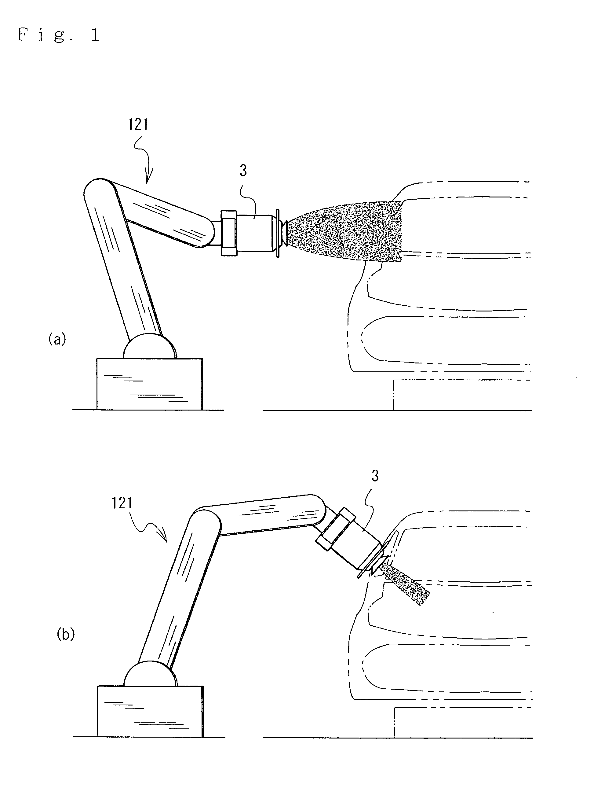
[0041]FIG. 1 illustrates an example of usage patterns of a coating machine 3. FIG. 1(a) shows the coating machine 3 used in a bell spray mode, and FIG. 1(b) shows the coating machine 3 used in a gun spray mode.

[0042]As shown in FIG. 1, the coating machine 3 serving as an example of the rotary atomizer according to the present invention is attached to a manipulator of a coating robot 121.

[0043]As shown in FIG. 1(a), in the coating machine 3 set in the bell spray mode, by rotating a bell cup and electrostatically charging the paint particles, the paint on the bell cup is atomized by the centrifugal force and the static electricity. In this mode, coating is performed with a diametrically large spray pattern. As shown in FIG. 1(b), at the time of finishing a local point or a small product, the coating machine 3 is changed into the gun spray mode so as to coat with a diametrically sma...


PUM


Abstract

A coating machine 3 serving as a rotary atomizer comprises a hollow unrotary paint nozzle shaft 5 provided in the center of a motor shaft 10 serving as its rotary shaft. The paint nozzle shaft 5 is provided at a tip thereof with a gun-spray paint nozzle 5g and a gun-spray air nozzle 5f on the outside of the gun-spray paint nozzle 5g in the diametrical direction, and a needle shaft 21 is disposed in a paint passage 5b in the paint nozzle shaft 5 so as to serve as a valve mechanism for selectively supplying paint to either a bell cup 4 or the gun-spray paint nozzle 5g.

Description

[0001]This application claims priority to Japanese Patent Application No. 2003-318788 filed 10 Sep. 2003, the content of which is incorporated herein by reference in its entirety.BACKGROUND OF THE INVENTION[0002]1. Field of the Invention[0003]The present invention relates to a rotary atomizer which atomizes paint so as to coat a target with the paint. In particular, the present invention relates to a rotary atomizer which can serve as both a bell spray and a gun spray.[0004]2. Related Art[0005]A rotary atomizer expands fluid paint on an inner surface of a rotating bell cup so as to atomize the paint by the centrifugal force, and electrifies the paint by static high voltage impressed on an atomizing head or the like and forms an electrostatic field formed between the atomizer and the grounded target, thereby performing electrostatic coating.[0006]There is a well-known conventional rotary atomizer having a cup-like shaped head which is controlled in rotary speed for switching its usag...

Claims


Application Information

Patent Timeline
Patent Type & Authority Patents(United States)
IPC IPC(8): B05B1/32B05B1/28B05B1/16B05D1/04B05B3/10B05B5/04B05B7/08
CPCB05B1/1681B05B3/1014B05B5/0426B05B7/0807
Inventor TANI, SHINJISAKAKIBARA, MASAHITOMITSUI, MICHIOKOBAYASHI, HIROSHINAGAI, KIMIYOSHIHOSODA, TOSHIO
Owner TOYOTA JIDOSHA KK
Why Eureka
Try Eureka