Fuel injection valve for internal combustion engines

a technology for internal combustion engines and fuel injection valves, which is applied in the direction of fuel injection apparatus, machine/engines, feed systems, etc., can solve the problems of shortening the switching time and aforementioned delay in building up the opening pressur

Inactive Publication Date: 2006-12-05
ROBERT BOSCH GMBH
View PDF14 Cites 24 Cited by
  • Summary
  • Abstract
  • Description
  • Claims
  • Application Information

AI Technical Summary

Benefits of technology

[0005]In a first advantageous feature of the subject of the invention, the throttle connection is embodied as an annular gap between the wall of the inner bore and the inner valve needle, on the end of the outer valve needle toward the combustion chamber. This embodiment of the throttle connection is easy to embody and moreover means that the inner valve needle cannot become stuck in the inner bore of the outer valve needle on the end toward the combustion chamber.
[0006]In a further advantageous feature, by means of a radial enlargement of the inner bore, a pressure vessel is formed in the outer valve needle, in which the pressure face of the inner valve needle is disposed and which can be made to communicate with the pressure chamber through the throttle connection. As a result of the embodiment of the pressure vessel, the size of the pressure face of the inner valve needle can be adjusted within wider ranges to obtain the desired opening force. It is also advantageous in this embodiment to provide a counterpart pressure face in the pressure vessel on the outer valve needle that is subjected to the fuel pressure in the pressure vessel and is oriented counter to the valve sealing face of the outer valve needle. This has the advantage that in the opening stroke motion of the outer valve needle, the full fuel pressure of the pressure chamber contacts the valve sealing face of the outer valve needle, while a lesser pressure still prevails in the pressure vessel, so that no counterpressure on the counterpart pressure face is produced. Conversely, in the closing motion, the injection pressure of the pressure chamber has built up in the pressure vessel, so that the counterpart pressure face of the outer valve needle is acted upon, and the hydraulic force on the valve sealing face of the outer valve needle is partly compensated for. As a result, the force on the outer valve needle in the opening direction is reduced, which speeds up the closing motion of the outer valve needle and thus decisively shortens the switching time.

Problems solved by technology

For this purpose, the pressure face of the inner valve needle can be made to communicate with the pressure chamber via a throttle connection, which leads to the aforementioned delay in building up the opening pressure.
As a result, the force on the outer valve needle in the opening direction is reduced, which speeds up the closing motion of the outer valve needle and thus decisively shortens the switching time.

Method used


Image

  • Fuel injection valve for internal combustion engines
  • Fuel injection valve for internal combustion engines
  • Fuel injection valve for internal combustion engines

Examples


Embodiment Construction

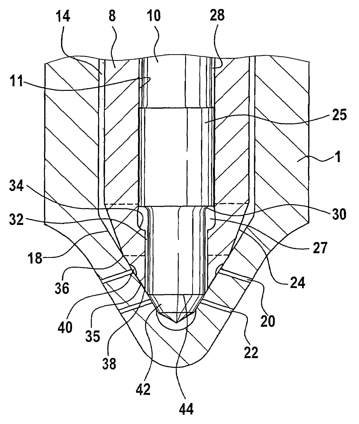
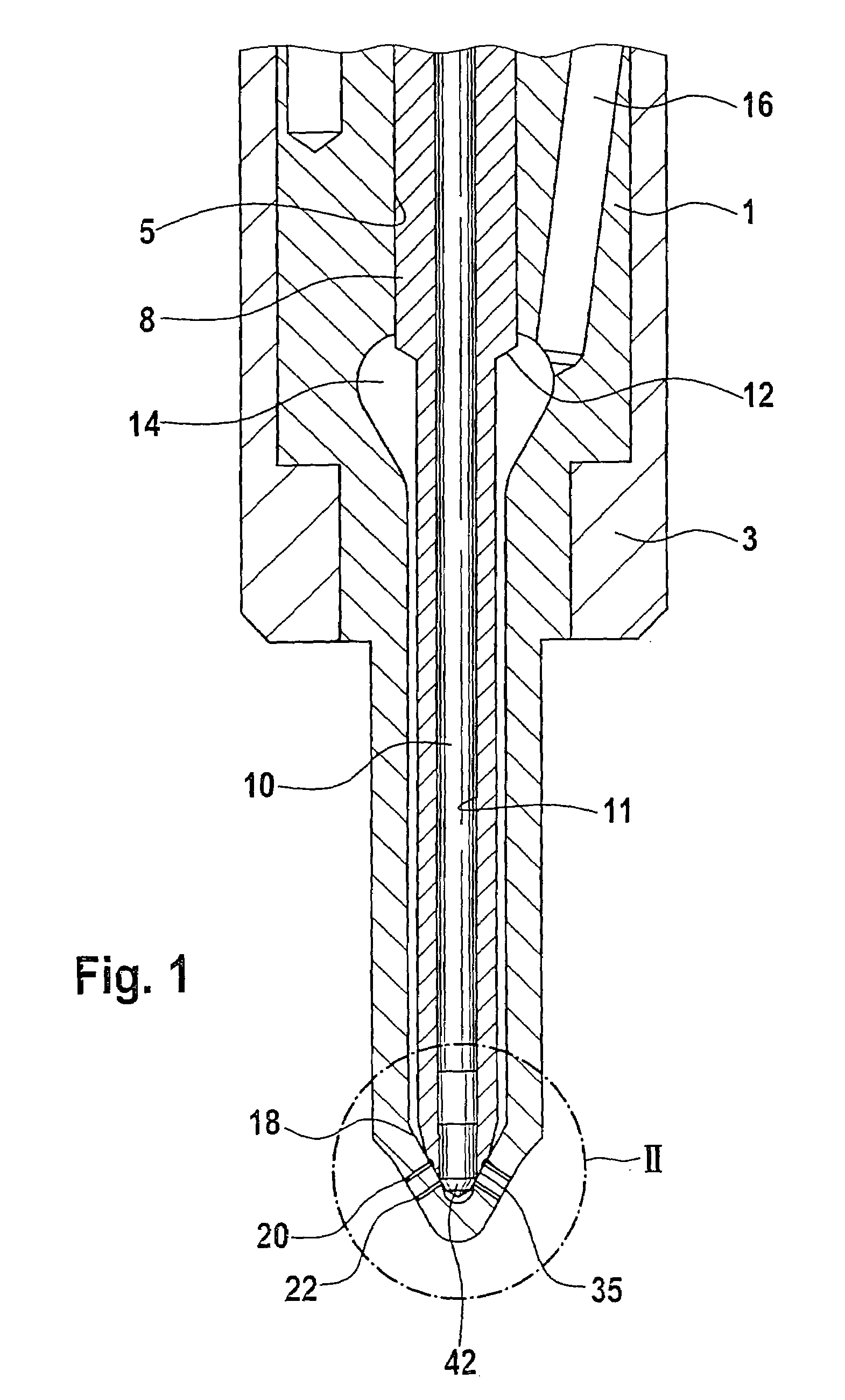
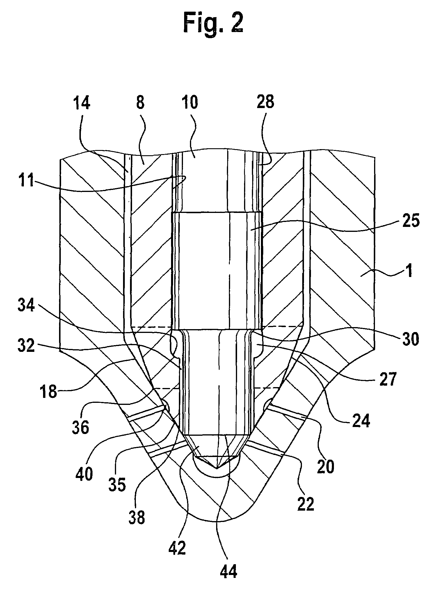
[0014]In FIG. 1, a fuel injection valve of the invention is shown in longitudinal section. The fuel injection valve has a valve body 1, which is pressed against a valve holder body, not shown in the drawing, by means of a tensioning nut 3. A bore 5 is embodied in the valve body 1 and is defined on its end toward the combustion chamber by a conical valve seat 18. A first row of injection openings 20 and a second row of injection openings 22, the latter located toward the combustion chamber, originate at the valve seat 18. In the installed position of the fuel injection valve in the engine, both rows of injection openings 20, 22 discharge into the combustion chamber of the engine. A pistonlike outer valve needle 8 is located in the bore 5 and is guided in the bore 5 in a portion facing away from the combustion chamber. Toward the valve seat 18, the outer valve needle 8 tapers, forming a pressure shoulder 12, and at its end toward the combustion chamber it merges with a sealing face 25...


PUM


Abstract

A fuel injection valve for internal combustion engines includes a valve body (1) in which a bore (5) is defined in one end, in which a first row of injection openings (20) and a second row of injection openings (22) are formed. In the bore (5), an outer valve needle (8) cooperates with the valve seat (18) for controlling the first row of injection openings (20); between the outer valve needle (8) and the wall of the bore (5), a pressure chamber (14) is formed. In the outer valve needle (8), an inner bore (11) is formed, in which an inner valve needle (10) is located and which cooperates with the valve seat (18) for controlling the second row of injection openings (22). A pressure shoulder (30) is formed on the inner valve needle. A hydraulic opening force is exerted on the inner valve needle (10); by its opening stroke, the outer valve needle (8) opens a throttle connection (32) from the pressure chamber (14) to the pressure shoulder (30) of the inner valve needle (10).

Description

CROSS-REFERENCE[0001]The invention described and claimed hereinbelow is also described in PCT / DE 2003 / 03624, filed Oct. 31, 2003 and DE 102 52 660.5, filed Nov. 11, 2002. This German Patent Application, whose subject matter is incorporated here by reference, provides the basis for a claim of priority of invention under 35 U.S.C. 119 (a)–(d).BACKGROUND OF THE INVENTION[0002]The invention is based on a fuel injection valve for internal combustion engines, of the kind known for instance from German Patent Disclosure DE 100 58 153 A1. The fuel injection valve shown there has a valve body in which a bore is embodied. On its end toward the combustion chamber, the bore is defined by a valve seat, in which a first row of injection openings and a second row of injection openings, the latter located on the combustion chamber side of the former, are embodied; the injection openings of both rows of injection openings discharge into the combustion chamber of the engine. an outer valve needle is ...

Claims


Application Information

Patent Timeline
Patent Type & Authority Patents(United States)
IPC IPC(8): F02M61/00F02M45/08F02M61/18F02M63/00
CPCF02M45/086F02M61/1873F02M2200/46
Inventor KUEGLER, THOMAS
Owner ROBERT BOSCH GMBH
Why Eureka
Try Eureka