Brake apparatus with orifices for restricting brake fluid pressure pulsation

a technology of brake fluid and orifice, which is applied in the direction of brake cylinders, braking systems, braking components, etc., can solve the problems of reducing undesirable noise of the brake apparatus, and achieve the effect of reducing undesirable nois

Inactive Publication Date: 2006-12-05
ADVICS CO LTD
View PDF24 Cites 10 Cited by
  • Summary
  • Abstract
  • Description
  • Claims
  • Application Information

AI Technical Summary

Benefits of technology

[0009]Accordingly, since the brake fluid pressure discharged from the pump decreases gradually, cavitations are not generated at lower reaches of the orifices because the brake fluid pressure does not rapidly decrease. As a result, the brake apparatus decreases undesirable noise.

Problems solved by technology

As a result, the brake apparatus decreases undesirable noise.

Method used


Image

  • Brake apparatus with orifices for restricting brake fluid pressure pulsation
  • Brake apparatus with orifices for restricting brake fluid pressure pulsation
  • Brake apparatus with orifices for restricting brake fluid pressure pulsation

Examples


first embodiment

[0017](First Embodiment)

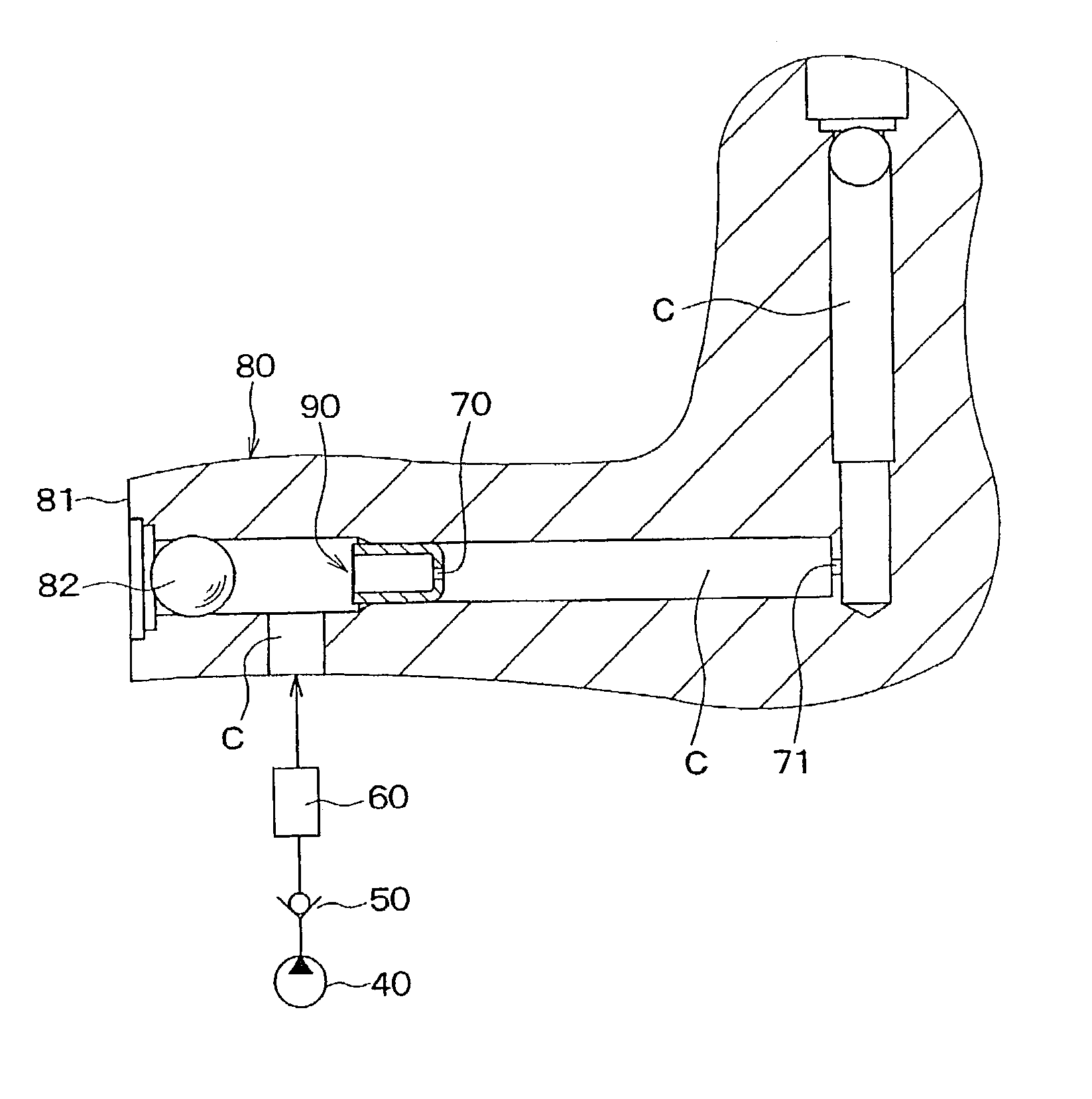
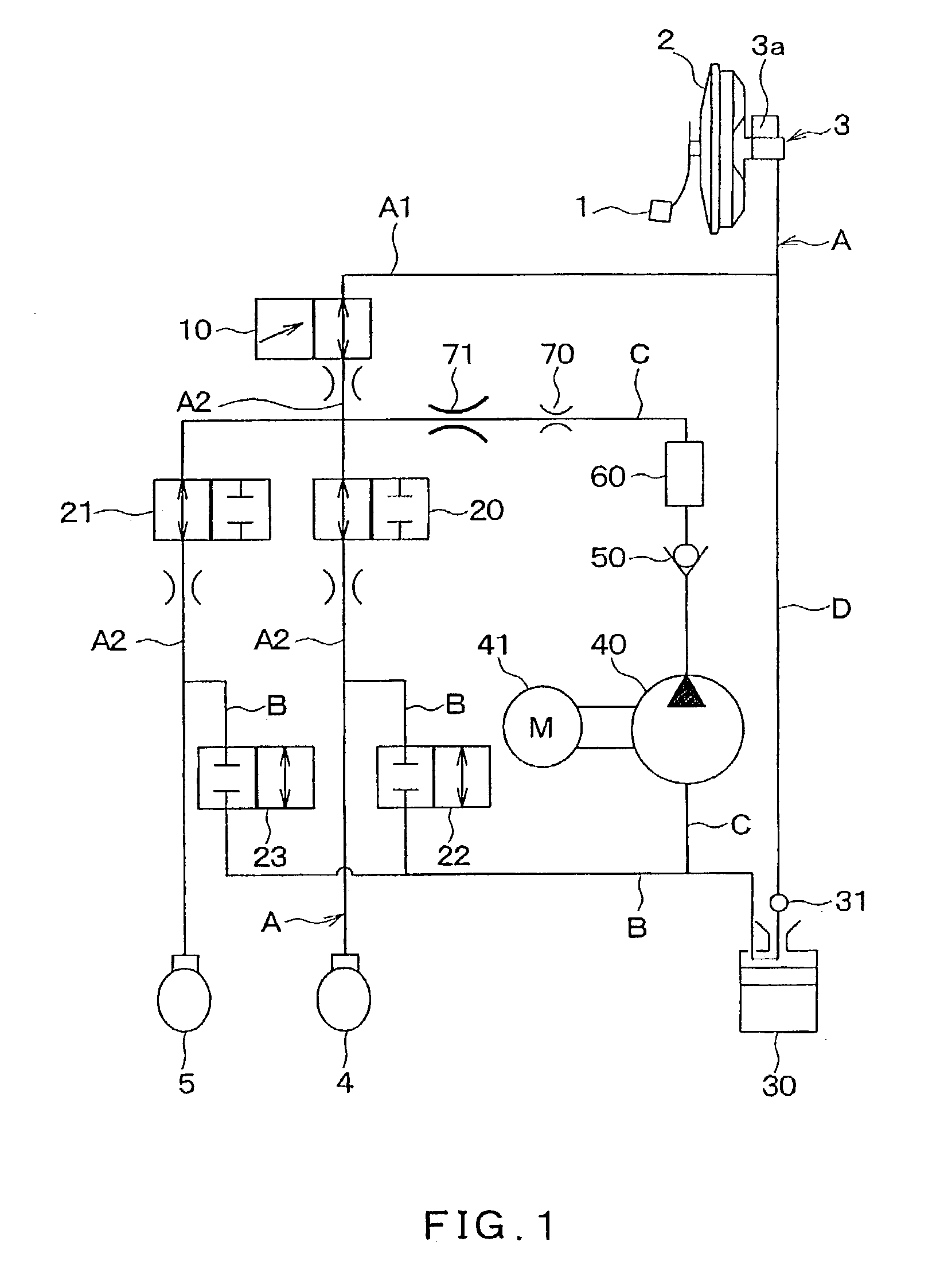
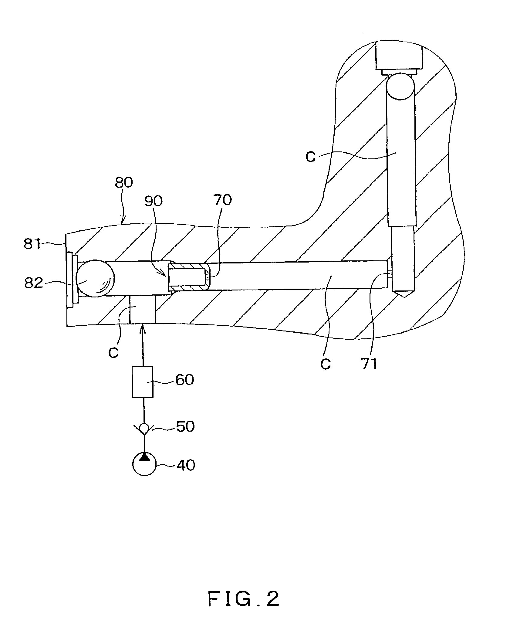
[0018]A first embodiment of the present invention is described with reference to FIGS. 1, 2. FIG. 1 shows an outline structure of a brake apparatus including orifices 70, 71. FIG. 2 shows an enlarged cross sectional view of the brake apparatus in the vicinity of the orifices 70, 71.

[0019]The structure of the brake apparatus will be described with reference to FIG. 1. In this embodiment, a brake apparatus is implemented in a front wheel drive vehicle provided with an X-shaped conduit configuration having a first conduit connecting wheel cylinders of a front right wheel and a rear left wheel, and a second conduit connecting wheel cylinders of a front left wheel and a rear right wheel.

[0020]As shown in FIG. 1, a brake pedal 1 is connected to a booster 2. The booster 2 boosts brake depression force and includes a pushrod for transmitting boosted depression force to a master cylinder 3. The master cylinder 3 generates master cylinder pressure when the pushrod push...

second embodiment

[0039](Second Embodiment)

[0040]A second embodiment of the present invention is described with reference to FIG. 3. FIG. 3 shows a cross sectional view on a discharge side of a pump conduit C of a brake apparatus including first and second orifices 70, 71. The other portions are the same as in the brake apparatus in the first embodiment.

[0041]In the present embodiment, the pump conduit C includes two conduits C11, C12 having first and second orifices 70, 71, respectively. The conduits C11, C12 are formed by drilling from surfaces of a housing 80. A cup-shaped brake fluid flow restriction portion 90 includes a bottom portion from which the orifice 71 is formed and is located in the conduit C11 by press-fitting. The orifice 70 is formed by penetrating a bottom portion of the conduit C12 to communicate with the conduit C11. According to the brake apparatus, the orifice 70, which is located on a closer side from the surface of the housing 80 relative to the orifice 71, is configured by a...

third embodiment

[0042](Third Embodiment)

[0043]A third embodiment of the present invention is described with reference to FIG. 4. FIG. 4 shows a cross sectional view on a discharge side of a pump conduit C of a brake apparatus including first and second orifices 70, 71. The other portions are the same as in the brake apparatus in the first embodiment.

[0044]In the present embodiment, the first and second orifices 70, 71 are integrated in a brake fluid flow restriction portion 90. The flow restriction portion 90 includes a cylindrical portion (a first flow restriction portion) 91 having the first orifice 70 and a cup-shaped portion (a second flow restriction portion) 92 having the second orifice 71. The cylindrical portion 91 is integrally press-fitted into the cup-shaped portion 92. The flow restriction portion 90 is press-fitted into the pump conduit C so as to be installed on a discharge side of the pump conduit C.

[0045]According to the brake apparatus of the present embodiment, the orifices 70, 71...


PUM


Abstract

In a brake apparatus, a pump sucks brake fluid and discharges the brake fluid through a pump discharge conduit. Orifices are connected in series with one another with respect to brake fluid flow discharged from the pump and restrict the brake fluid flow. Because the orifices are formed for restricting brake fluid pulsation, the brake fluid pressure discharged from the pump decreases gradually. Therefore, cavitations are not generated at lower reaches of the orifices because the brake fluid pressure does not decrease rapidly. As a result, the brake apparatus decreases or restricts undesirable noise.

Description

CROSS REFERENCE TO RELATED APPLICATIONS[0001]This application is based upon and claims the benefit of Japanese Patent Application No. 2002-43352 filed on Feb. 20, 2002, the contents of which are incorporated herein by reference.FIELD OF THE INVENTION[0002]The present invention relates to vehicle brake apparatuses, and specifically to a brake apparatus with a pump that discharges brake fluid in a manner that decreases brake fluid pulsation.BACKGROUND OF THE INVENTION[0003]A typical vehicle brake apparatus performs a primary check period to check for malfunctions of components thereof such as a pump and electromagnetic valves by activating the components when an engine starts. Thus, reliability of the brake apparatus increases. During the primary check period, the brake fluid circulates through the pump, an orifice formed at a fluid discharge port of the pump, the electromagnetic valves, a reservoir and the pump.[0004]The above mentioned orifice is formed for restricting brake fluid p...

Claims


Application Information

Patent Timeline
Patent Type & Authority Patents(United States)
IPC IPC(8): B60T8/36B60T8/40B60T8/42B60T8/48B60T17/02B60T17/04
CPCB60T8/365B60T8/367B60T8/4068B60T8/4872B60T17/02B60T17/04B60T8/4291Y10S303/10
Inventor INAGE, SHOZOKINOSHITA, HIDEHIROYOSHIOKA, NOBUHIKOYAMAGUCHI, TAKAHIRO
Owner ADVICS CO LTD
Why Eureka
Try Eureka