Lamp cooling device and projection display apparatus

Inactive Publication Date: 2006-10-19
SONY CORP
View PDF1 Cites 32 Cited by
  • Summary
  • Abstract
  • Description
  • Claims
  • Application Information

AI Technical Summary

Benefits of technology

[0008] It is desirable to provide a lamp cooling device which produces low noise and is highly reliable in operation, and a projection display apparatus incorporating such a lamp cooling device.
[0012] The gas cooled while flowing through the duct and flowing back into the intralamp space is lower in temperature than the gas flowing out of the intralamp space, and cools the light emission source. Having cooled the light emission source, the gas becomes higher again in temperature and flows again into the duct. While flowing through the duct, the gas is cooled again and flows back into the intralamp space. Therefore, the gas is circulated through the duct and the intralamp space. As a result, the light emission source is controlled into a desired temperature range, thereby increasing the service life of the lamp and allowing the lamp to emit a desired amount of light continuously.
[0014] With this structure, no dust and dirt particles enter from outside of the lamp into the intralamp space, and block light emitted from the light emission source and hence reduce the luminance of the lamp. Even if gas flow noise occurs when the gas flows into the intralamp space through the gas inlet and also from the intralamp space through the gas outlet, and if rupture sounds are produced when the light emission tube is ruptured, since the gas flow noise and the rupture sounds are generated within a duct assembly isolated from the external space, those noise and sounds are prevented from leaking out. As a consequence, undesirable noise of the projection display apparatus is greatly reduced. Fragments of the ruptured light emission tube and a harmful material, e.g., mercury if the lamp is a mercury lamp, are also prevented from being discharged out.
[0015] According to the present invention, the gas in the intralamp space is circulated through the duct in isolated relation to the space outside of the lamp, and is directly introduced into the intralamp space to cool the light emission source. Therefore, no foreign matter enters the intralamp space from outside of the lamp, and no noise leaks from the intralamp space into the space outside of the lamp. As a result, the lamp is effectively cooled without damage to its quality for achieving an increased service life.

Problems solved by technology

However, introducing ambient air into the space in the lamp 1 in which the light emission source 3a and the sealed portion 3b of the bulb tip end are located poses the following problems, such as dust and dirt contained in the ambient air enter the space in the lamp 1, blocking light thereby to reduce the amount of light emitted from the lamp, i.e., to reduce the luminance of the lamp 1.
Moreover, air as it flows through the openings or air inlet / output ports 52, 53 tends to cause noise.

Method used


Image

  • Lamp cooling device and projection display apparatus
  • Lamp cooling device and projection display apparatus
  • Lamp cooling device and projection display apparatus

Examples


first embodiment

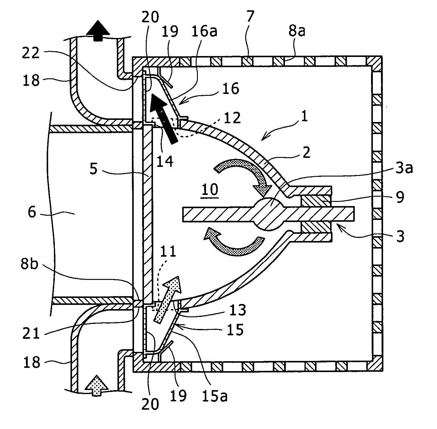
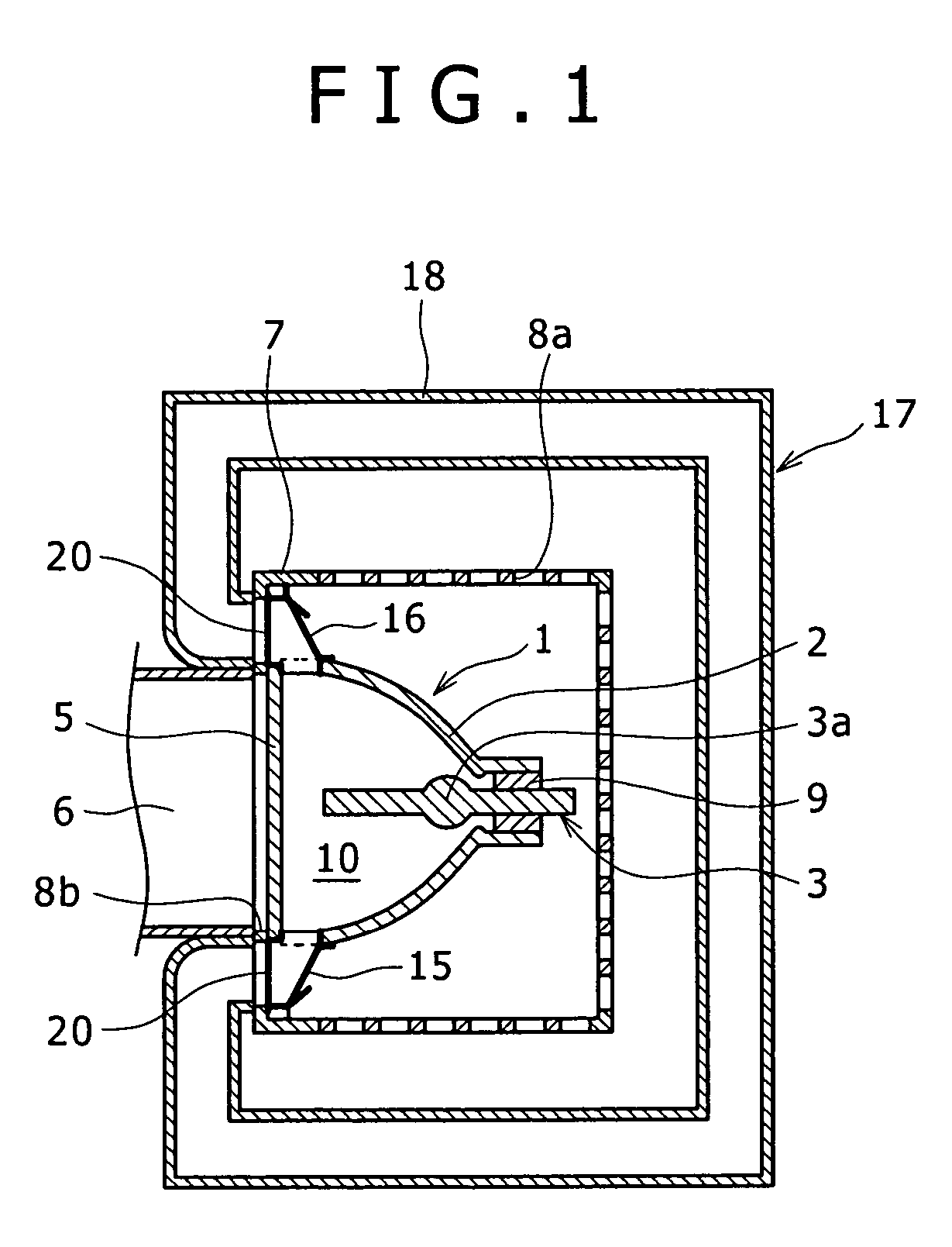
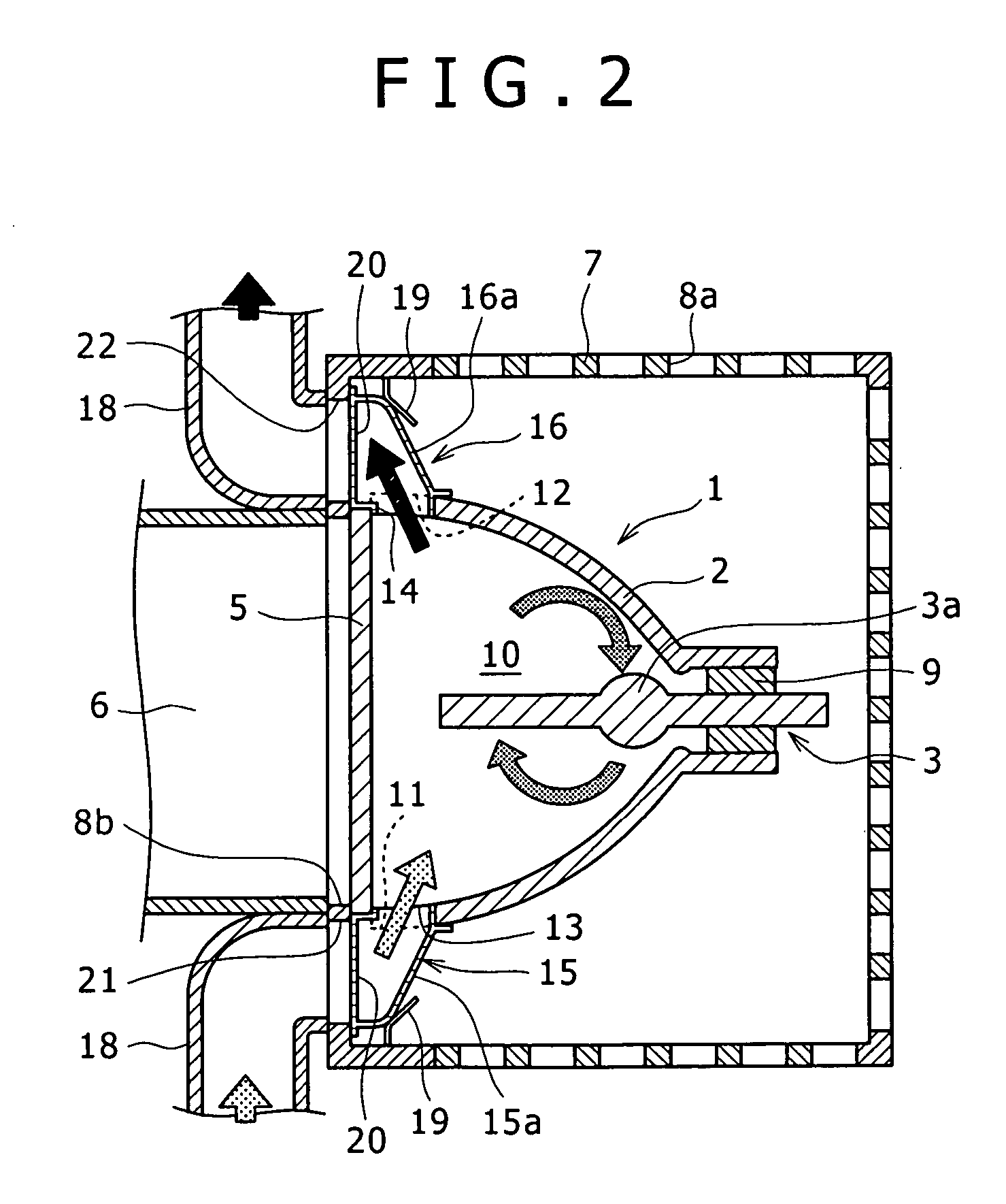
[0039]FIG. 1 shows in cross section a lamp cooling device and a lamp according to a first embodiment of the present invention, and FIG. 2 shows in enlarged fragmentary cross section the lamp cooling device shown in FIG. 1. The lamp cooling device according to the first embodiment as shown in FIGS. 1 and 2 is incorporated in a projection display apparatus which has an optical unit 6 for processing rays of light emitted from a lamp 1 and an image produced by the optical unit 6 is projected at an enlarged scale onto a projection surface by a projection lens. The projection display apparatus may be a projector for projecting images onto the front surface of a screen, a rear projection television set having a projector for projecting images onto the rear surface of a screen, or the like. The optical unit 6 has a liquid crystal display unit or a DMD (Digital Micromirror Device) for generating images.

[0040] The lamp 1 may include a metal halide lamp, a high-pressure mercury lamp, a haloge...

second embodiment

[0067] A lamp cooling device according to a second embodiment of the present invention will be described below with reference to FIG. 4. Those parts of the lamp cooling device according to the second embodiment which are identical to those of the lamp cooling device according to the first embodiment are denoted by identical reference characters, and will not be described in detail below.

[0068] According to the second embodiment, as shown in FIG. 4, the lamp cooling device additionally has a cooling unit 24 disposed in the duct 18 for cooling the gas which is flowing through the duct 18. The cooling unit 24 is located substantially intermediate between the air outlet 12 and the air inlet 11. The cooling unit 24 may include a heat sink of a material having an excellent heat radiating capability, e.g., aluminum or copper, with or without fins, a heat pipe, a heat absorber, a heat exchanger, or the like. The cooling unit 24 is effective to efficiently cool the gas in the duct 18 withou...

third embodiment

[0072] A lamp cooling device according to a second embodiment of the present invention will be described below with reference to FIG. 5. Those parts of the lamp cooling device according to the third embodiment which are identical to those of the lamp cooling devices according to the first and second embodiments are denoted by identical reference characters, and will not be described in detail below.

[0073] According to the third embodiment, as shown in FIG. 5, the lamp cooling device has a second cooling unit for performing a heat exchange with the cooling unit 24. The second cooling unit includes a liquid-cooling jacket 28, a cooling liquid circulating pipe 30, a cooling liquid circulating pump 29, and a heat radiator 31 such as a heat sink or the like similar to the cooling unit 24. The cooling liquid flowing through the cooling liquid circulating pipe 30 is heated by the cooling unit 24 in the liquid-cooling jacket 28 and flows to the heat radiator 31, which radiates heat from th...


PUM


Abstract

Disclosed herein is a lamp cooling device for cooling a lamp including a light emission source for emitting light, a front transparent plate, a reflector for reflecting light emitted by the light emission source toward the front transparent plate, the light emission source being disposed in an intralamp space surrounded by the front transparent plate and the reflector, said lamp cooling device including: a duct having joint ports defined in respective opposite ends thereof and communicating with said intralamp space, said duct having a continuously extending portion between said opposite ends which is disposed in a space outside of said intralamp space, for circulating a gas through said duct and said intralamp space in isolated relation to the space outside of said intralamp space.

Description

CROSS REFERENCES TO RELATED APPLICATIONS [0001] The present invention contains subject matter related to Japanese Patent Application 2005-086346 filed with the Japanese Patent Office on Mar. 24, 2005, the entire contents of which being incorporated herein by reference. BACKGROUND OF THE INVENTION [0002] The present invention relates to a lamp cooling device for cooling a lamp for use as a light source for projection display apparatus, and a projection display apparatus, and more particularly to a lamp cooling device for directly air-cooling an intralamp space surrounded by a reflector and a front transparent plate, and a projection display apparatus. [0003]FIGS. 20 and 21 of the accompanying drawings show a structure of a general lamp 1 for use as a light source for projection display apparatus. The lamp 1 has a light emission source 3a including a glass tube filled with a discharge gas. The light emission source 3a is positioned in a space surrounded and sealed from the exterior by...

Claims


Application Information

Patent Timeline
IPC IPC(8): F21V29/00
CPCF21V29/02F21V29/30G03B21/16F21V29/59F21V29/60F21V29/67F21V29/83
Inventor HAGA, MOTOHISAYAMAOKA, KEITERASAKI, KAZUYAITO, YUKIOOHKUBO, TAKUJIHASEGAWA, HIROSHIYAMASHITA, KATSUHIROOONISHI, MASATAKAYONEYA, DAIMIWA, SATORUNAKAGAWA, SHIGEYASU
Owner SONY CORP
Why Eureka
Try Eureka