Nirs sensor assembly including electrically conductive and optically transparent EMI shielding

a sensor and optical shielding technology, applied in the field of nirs sensor assembly including electrically conductive and optically transparent emi shielding, can solve the problems of nirs sensor cost to manufacture, signal interference from electromagnetic interference sources, and the inability to yield useful information with respect to cerebral oxygenation, etc., to achieve the effect of reducing undesirable nois

Active Publication Date: 2014-02-20
EDWARDS LIFESCIENCES CORP
View PDF7 Cites 19 Cited by
  • Summary
  • Abstract
  • Description
  • Claims
  • Application Information

AI Technical Summary

Benefits of technology

[0011]According to an aspect of the present invention, a NIRS sensor assembly for non-invasive monitoring of blood oxygenation levels in a subject's body is provided. The sensor assembly comprises at least one light source, at least one light detector, electromagnetic interference (EMI) shielding, and a light blocking sheet. The light source is operable to emit light signals of a plurality of different wavelengths, including those in the near-infrared range. The light detector is operable to detect light emitted by the light source and passed through the subject's body tissue. The shielding, which is disposed around at least a portion of the light detector, attenuates local EMI and thereby reduces undesirable noise within the light detector signals. The light blocking sheet is disposed relative to at least one of the light detectors, and includes an aperture sized to mate with the active area of the light detector with which it is disposed.

Problems solved by technology

In the case of a mean optical path that non-invasively accesses brain tissue, the attenuation attributable to the extra cerebral tissue does not yield useful information with respect to the cerebral oxygenation.
A problem common to all NIRS sensors is signal interference from electromagnetic interference (EMI) sources.
Another problem common to all NIRS sensors is the cost to manufacture.
NIRS sensors are typically disposed of after use, so the cost of the sensor is an important factor in the cost of the monitoring.

Method used


Image

  • Nirs sensor assembly including electrically conductive and optically transparent EMI shielding
  • Nirs sensor assembly including electrically conductive and optically transparent EMI shielding
  • Nirs sensor assembly including electrically conductive and optically transparent EMI shielding

Examples


Embodiment Construction

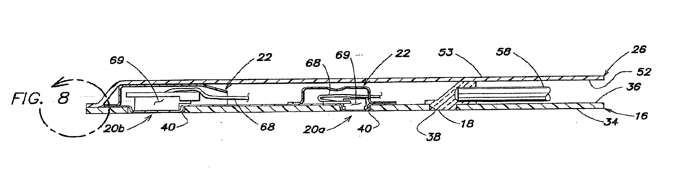
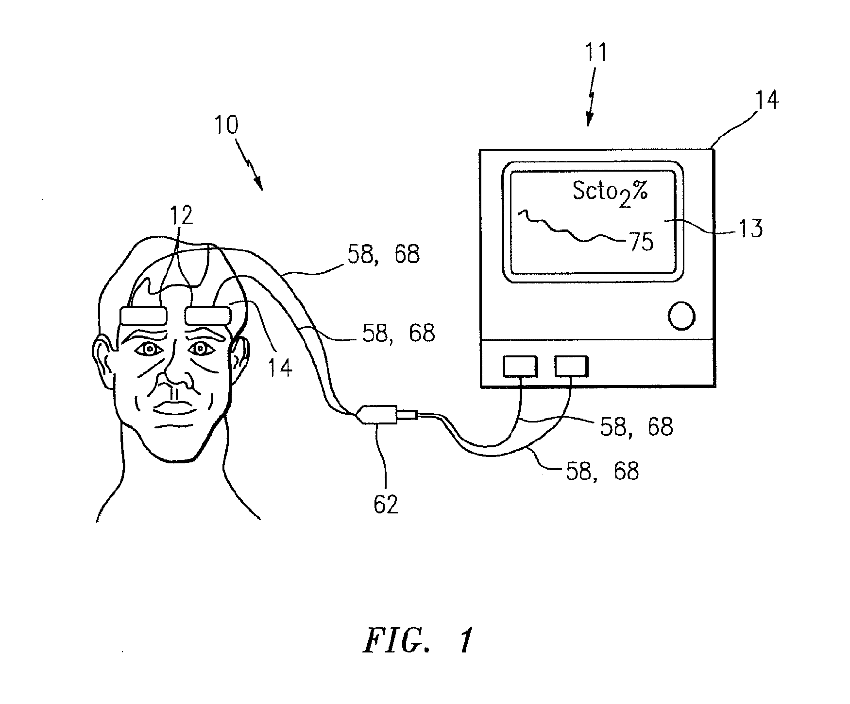
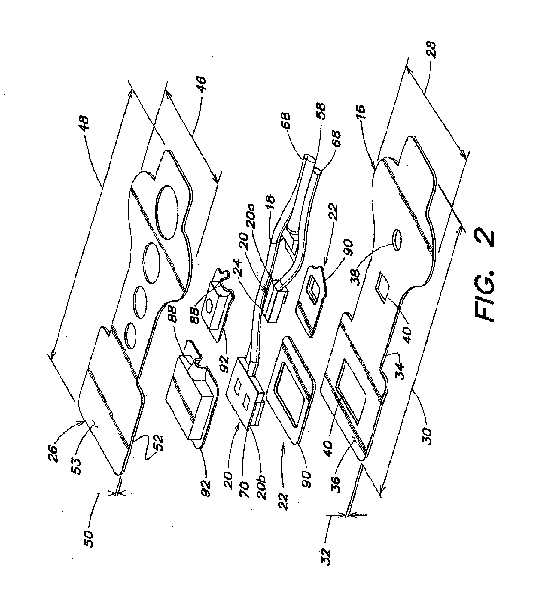
[0026]Referring now to the drawings, a near infrared spectroscopy (NIRS) system 10 includes one or more NIRS sensor assemblies 12 connected to a base unit 11. The base unit 11 includes a display 13, operator controls, and a processor 14 for providing signals to and / or receiving signals from the NIRS sensor assembly(ies) 12. The processor 14 is adapted (e.g., programmed) to selectively perform the functions necessary to operate the sensor(s). It should be noted that the functionality of the processor 14 may be implemented using hardware, software, firmware, or a combination thereof. A person skilled in the art would be able to program the processor 14 to perform the functionality described herein without undue experimentation. For purposes of providing a detailed description of the present NIRS sensor assembly 12, the sensor assembly 12 will be described herein as being used in connection with the NIRS system described in U.S. Pat. No. 6,456,862 and U.S. Pat. No. 7,072,701, which are...


PUM


Abstract

A near infrared spectrophotometric sensor assembly for non-invasive monitoring of blood oxygenation levels in a subject's body is provided. The assembly includes at least one light source, at least one light detector operable to detect light emitted by the light source, an electromagnetic interference shielding disposed around at least a portion of the light detector, wherein the electromagnetic interference shielding includes an electrically conductive substrate that is optically transparent, and one or both of a light blocking sheet disposed relative to at least one of the light detectors and an encapsulating material.

Description

[0001]Applicant hereby claims priority benefits under 35 U.S.C. §119(e) of U.S. Provisional Patent Application No. 61 / 442,273 filed Feb. 13, 2011, and U.S. Provisional Patent Application No. 61 / 546,821 filed Oct. 13, 2011, the disclosures of which are herein incorporated by reference.BACKGROUND OF THE INVENTION[0002]1. Technical Field[0003]This invention relates to methods and apparatus for non-invasively determining biological tissue oxygenation utilizing near-infrared spectroscopy (NIRS) techniques in general, and to sensors for use with such techniques in particular.[0004]2. Background Information[0005]Near-infrared spectroscopy is an optical spectrophotometric method that can be used to continuously monitor tissue oxygenation. The NIRS method is based on the principle that light in the near-infrared range (700 nm to 1,000 nm) can pass easily through skin, bone and other tissues where it encounters hemoglobin located mainly within micro-circulation passages; e.g., capillaries, ar...

Claims


Application Information

Patent Timeline
Patent Type & Authority Applications(United States)
IPC IPC(8): A61B5/1455
CPCA61B5/14552A61B5/0075A61B5/14553A61B2562/182
Inventor DALENE, MATTHEWDUFFY, KAREN
Owner EDWARDS LIFESCIENCES CORP
Why Eureka
Try Eureka