Device for pressing a transfer element

a transfer element and device technology, applied in the direction of steering gears, steering parts, power driven steering, etc., can solve problems such as unsatisfactory noise, and achieve the effect of significantly reducing unsatisfactory nois

Inactive Publication Date: 2012-07-26
ZF LENKSYST
View PDF21 Cites 4 Cited by
  • Summary
  • Abstract
  • Description
  • Claims
  • Application Information

AI Technical Summary

Benefits of technology

[0004]It is therefore the object of the invention to improve a device of the type mentioned above to the effect that undesirable noise is considerably reduced.

Problems solved by technology

During driving operations of the motor vehicle, however, the worm is repeatedly pressed against the pressure piece, so that the spring unit strikes against a housing, which can generate undesirable noise.

Method used


Image

  • Device for pressing a transfer element
  • Device for pressing a transfer element
  • Device for pressing a transfer element

Examples


Embodiment Construction

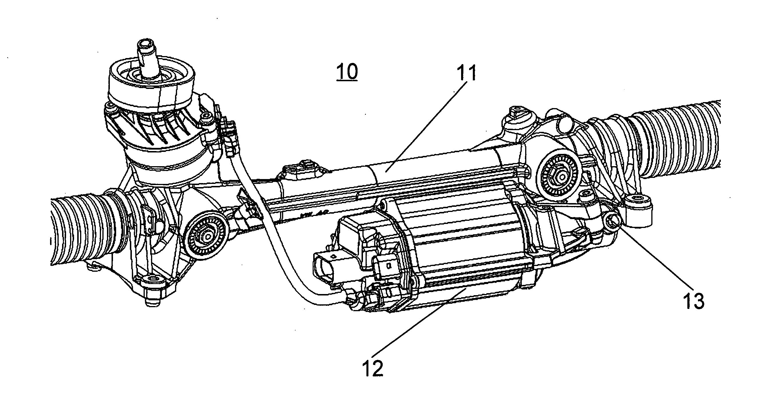
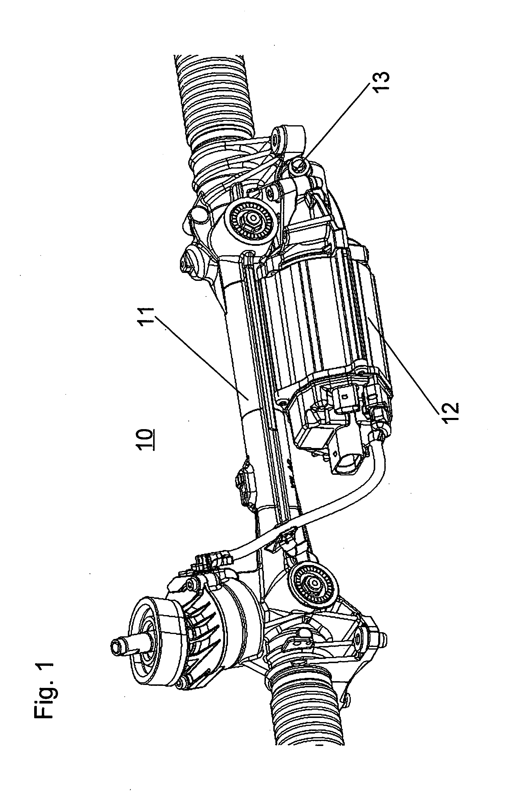
[0025]FIG. 1 shows an electrical steering system 10, comprising a housing region 11, behind which a steering rack is hidden, a housing region 12, behind which an electric motor is mounted, and a device 13 for pressing on a transmission element, which is not shown in detail here.

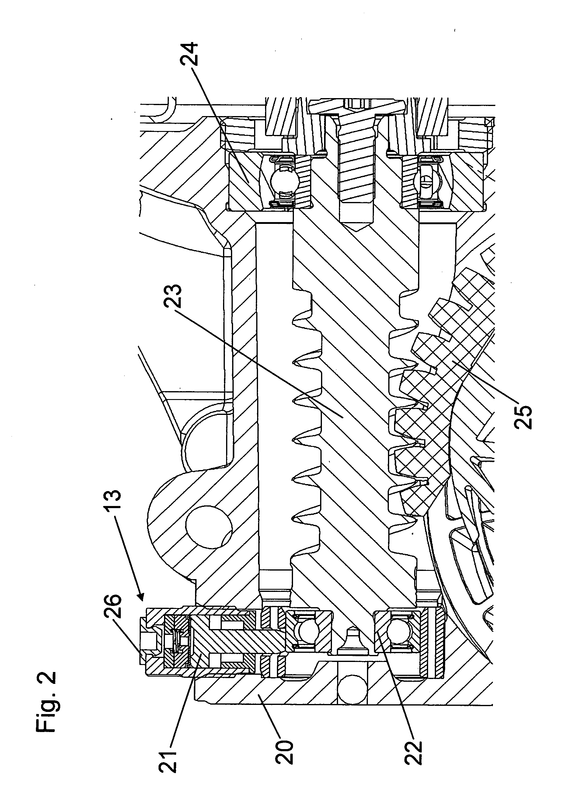
[0026]The device 13 is screwed into a gearbox housing 20 (see FIG. 2). A pressure piece 21, which is provided in the device 13, presses onto a bearing 22, which at one end is disposed on a transmission element 23 designed as a worm. At the other end, a bearing 24 is provided on the transmission element 23, the bearing being designed so as to allow the transmission element 23 to perform pivoting movements. The bearing 22 can consequently carry out smaller movements in the vertical direction.

[0027]The transmission element 23 designed as a worm engages with a transmission element 25 designed as a worm wheel. The device 13 consequently presses the transmission element 23 against the transmission element 25, where...


PUM


Abstract

Described is a device for pressing a first transmission element onto a second transmission element engaging with the first transmission element, in particular for a steering system of a motor vehicle, comprising a pressure piece which can be loaded in the direction of the first transmission element and is displaceably guided in a housing. The devices known from the prior art can cause undesirable noise during driving operations. The device according to the invention thus comprises an adjustment unit for minimizing play occurring between the first transmission element and the second transmission element.

Description

[0001]This is a Continuation of U.S. National Stage of PCT / EP2010 / 060940 filed July 28, 2010.BACKGROUND OF THE INVENTION[0002]The invention relates to a device for pressing a first transmission element onto a second transmission element engaging with the first transmission element, in particular for a steering system of a motor vehicle, comprising a pressure piece which can be loaded in the direction of the first transmission element and is displaceably guided in a housing.[0003]A device of the type in question is described in DE 102 30 600 B4. This device is provided with a spring unit, which presses the pressure piece against a worm. The worm can thus be optimally pressed against a worm wheel, whereby as little play and as little wear as possible are created between the worm and the worm wheel. During driving operations of the motor vehicle, however, the worm is repeatedly pressed against the pressure piece, so that the spring unit strikes against a housing, which can generate und...

Claims


Application Information

Patent Timeline
Patent Type & Authority Applications(United States)
IPC IPC(8): F16H35/06
CPCB62D3/123B62D5/0409Y10T74/19565F16H2057/0213F16H55/283F16H55/24
Inventor BAREIS, HELMUT
Owner ZF LENKSYST
Why Eureka
Try Eureka