Grinding wheel

a technology of grinding wheel and grinding plate, which is applied in the direction of gear teeth, manufacturing tools, manufacturing apparatus, etc., can solve the problems of reducing the grinding effect, hard and laborious for operators to operate and control the grinding plate, etc., and achieves the effect of less strength and easy operation of the grinding pla

Inactive Publication Date: 2006-12-05
STORM PNEUMATIC TOOL CO LTD
View PDF8 Cites 19 Cited by
  • Summary
  • Abstract
  • Description
  • Claims
  • Application Information

AI Technical Summary

Benefits of technology

[0005]It is therefore a primary object of the present invention to provide a grinding wheel having an internal buffer member made of deformable soft material. When grinding a work piece with a grinder, the shock produced in operation can be effectively absorbed by the buffer member. Therefore, an operator can more easily operate the grinder with less strength. Furthermore, when the grinding wheel is rotated at high speed, the centrifugal force will make the buffer member deform, whereby the circumference of the buffer member will lean on the wall of the shaft hole of the grinding wheel. Accordingly, the buffer member can support the working section of the grinding wheel.
[0006]It is a further object of the present invention to provide the above grinding wheel in which an annular connecting section is formed along outer circumference of the fixing section to connect with the annular working section of the ring-shaped wheel. Therefore, the working section will not be interrupted by the projecting sections of the fixing caps. Accordingly, the working section can be manufactured without any notch free from the steel wire.

Problems solved by technology

Therefore, it is hard and laborious for the operator to operate and control the grinder.
This will reduce the grinding effect.

Method used


Image

  • Grinding wheel
  • Grinding wheel
  • Grinding wheel

Examples


Embodiment Construction

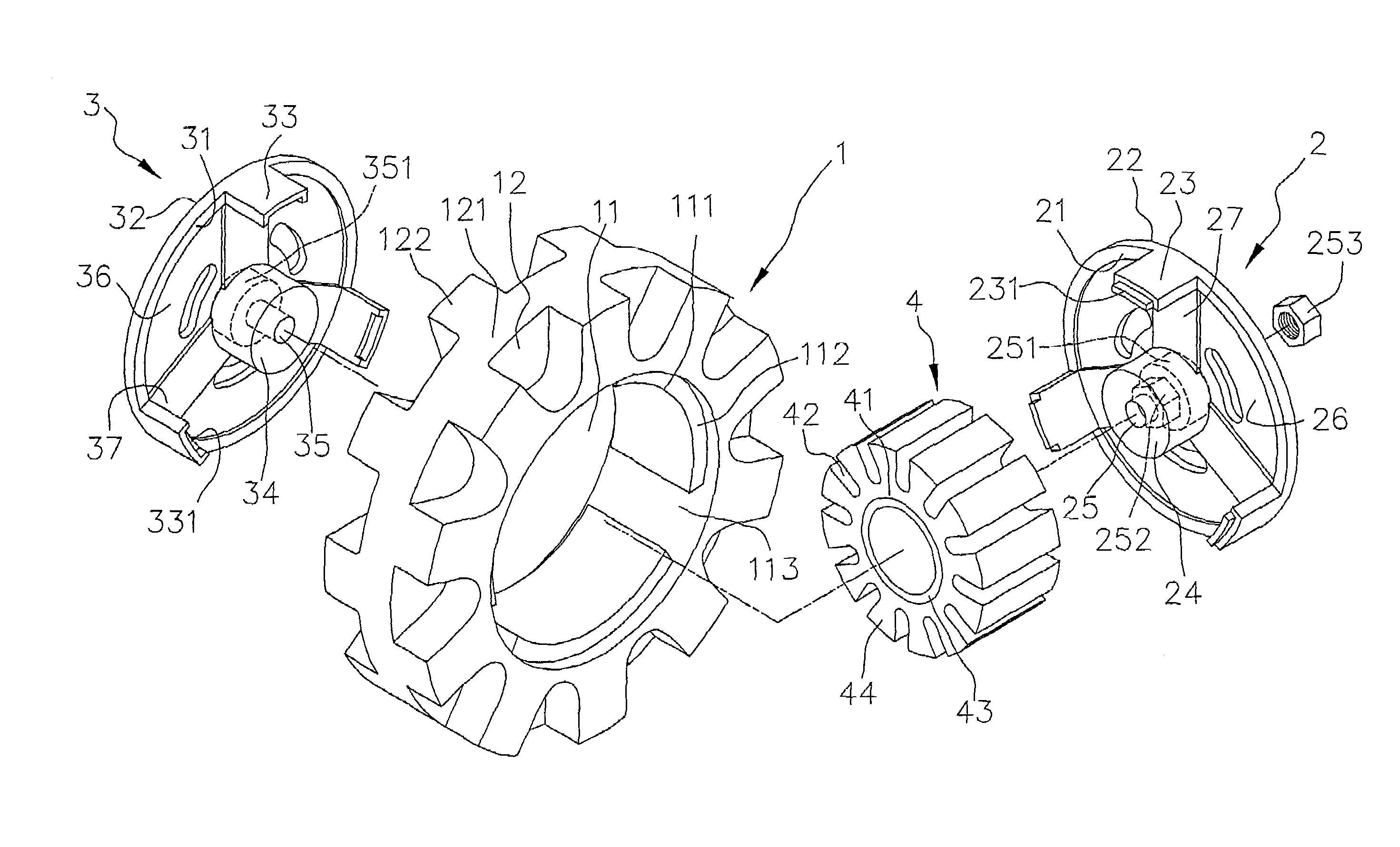
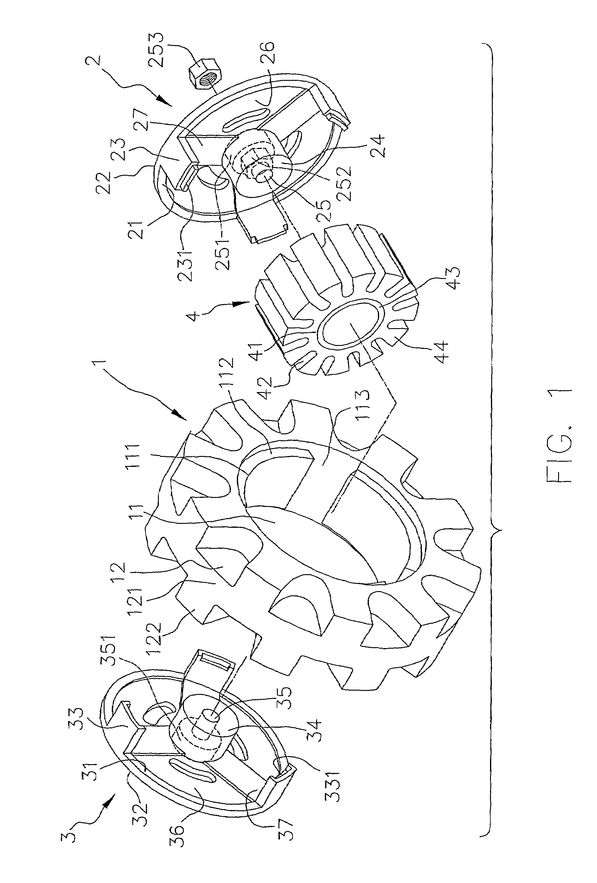
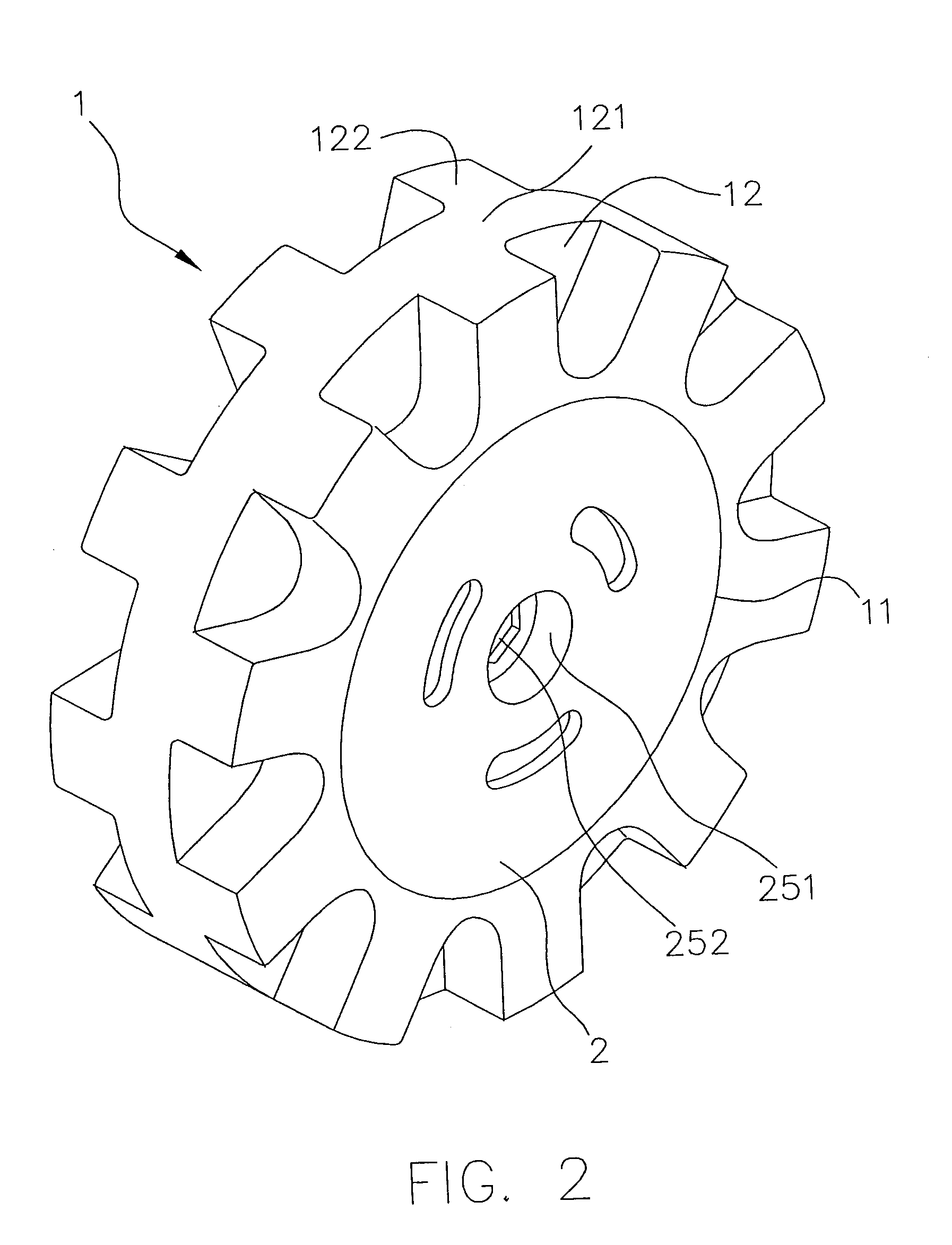
[0023]Please refer to FIGS. 1 to 5. The grinding wheel structure of the present invention includes a ring-shaped wheel 1 having a fixing section 11. A working section 12 is formed along outer circumference of the fixing section 11. The working section 12 and the fixing section 11 of the ring-shaped wheel 1 are integrally formed and made of the same material such as rubber.

[0024]The fixing section 11 of the ring-shaped wheel 1 is formed with a shaft hole 111. Two annular grooves 112 are respectively formed on two sides of the ring-shaped wheel 1 along the circumference of the shaft hole 111. Multiple axially extending recesses 113 are formed on inner circumferential wall of the shaft hole 111. The recesses 113 extend from one side of the ring-shaped wheel 1 to the other side thereof and communicate with the annular grooves 112. An annular rib section 121 is formed on the working section 12 of the ring-shaped wheel 1 at the middle of the axis of the ring-shaped wheel 1. Multiple proje...


PUM


Abstract

A grinding wheel including a ring-shaped wheel, a first fixing cap, a second fixing cap and a buffer member. The ring-shaped wheel has a fixing section and a working section formed along outer circumference of the fixing section. The first and second fixing caps are respectively mounted on two sides of the fixing section. The buffer member is positioned between the first and second fixing caps for reducing shock produced in operation. The circumference of the buffer member is formed with multiple movable vanes. When the grinding wheel is rotated at high speed, the centrifugal force will deform the movable vanes of the buffer member to lean on the ring-shaped wheel for supporting the working section thereof.

Description

BACKGROUND OF THE INVENTION[0001]The present invention is related to a grinding wheel installable on a grinder. The grinding wheel is equipped with an internal buffer member for reducing shock.[0002]FIGS. 8 to 10 show a conventional grinding wheel structure installed on a grinder. The grinding wheel structure includes a ring-shaped wheel 6, a first fixing cap 7 and a second fixing cap 8. The inner circumference of the ring-shaped wheel 6 has a fixing section 61. A working section 62 is arranged on outer circumference of the fixing section 61. The fixing section 61 is fixed with the first and second fixing caps 7, 8.[0003]The above grinding wheel is installable on a grinder for grinding a work piece. When grinding a hard work piece such as a metal piece with irregular surface, a shocking force will be transmitted to an operator. Therefore, it is hard and laborious for the operator to operate and control the grinder.[0004]Moreover, each fixing cap 7, 8 has a support ring 71, 81. Multi...

Claims


Application Information

Patent Timeline
IPC IPC(8): B24B45/00F16F15/00
CPCB24D5/16B24D7/16F16F15/12F16F15/124
Inventor SUN, YUNG-YUNGCHENG, CHUAN-CHING
Owner STORM PNEUMATIC TOOL CO LTD
Why Eureka
Try Eureka