Interconnect for solid oxide fuel cells

Inactive Publication Date: 2006-12-05
BALLARD POWER SYSTEMS
View PDF27 Cites 7 Cited by
  • Summary
  • Abstract
  • Description
  • Claims
  • Application Information

AI Technical Summary

Benefits of technology

[0014]The present invention provides a solid oxide fuel cell stack design that decouples the requirements of oxidation resistance, oxide scale electron conductance, and close coefficient of thermal expansion match with other stack components. This decoupling of requirements widens the range of metallic materials that can be used for the interconnect, especially on the cathode side, and enables the use of metallic materials that can provide lifetimes in excess of 40,000 hours.
[0015]According to the invention, a fuel cell assembly is provided which comprises a plurality of fuel cells each having an anode layer, an electrolyte layer, and a cathode layer, the fuel cells each having a first effective thermal expansion coefficient; a plurality of bipolar pla

Problems solved by technology

Currently, the lack of stable, long-life (>40,000 hours), metallic interconnects for the cathode side of the stack, is a serious weakness of planar solid oxide fuel cells, because existing metal alloys cannot meet the thermal expansion, oxidation resistance, and electron conductance requirements simultaneously.
However the ceramic is very expensive, has low toughness and is difficult to manufacture as a suitable interconnector.
Commercial grades of ferritic steels may have suitable oxidation resistance at temperatures less than about 600° C. or for short lifetimes, but do not have the required oxidation resistance to last for 40,000 hours, or longer, due to the increasing ohmic resistance across the oxide scale with time under load.
However, elements known to improve oxidation resistance, such as Al and Si, also tend to reduce the oxide conductivity and incre

Method used


Image

  • Interconnect for solid oxide fuel cells
  • Interconnect for solid oxide fuel cells
  • Interconnect for solid oxide fuel cells

Examples


Example

Example 1

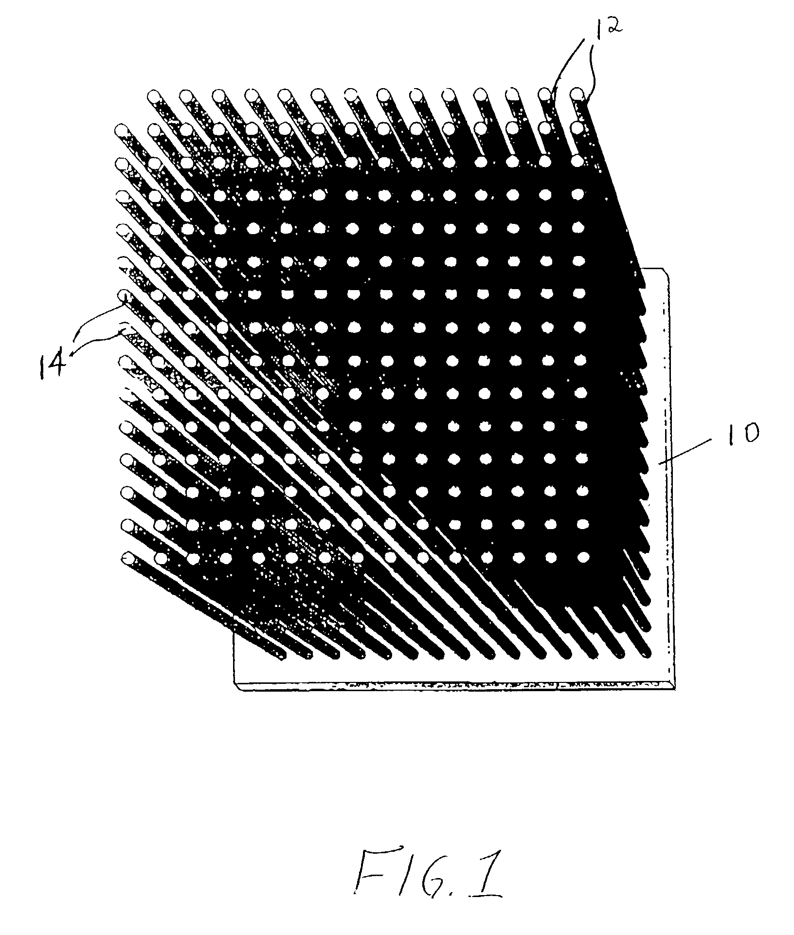
[0066]Samples of separator material, approximately 25 mm (1″) square, were cut from a ferritic stainless steel, sheet alloy (E-BRITE®) and coated with a Ni-based braze alloy (NICROBRAZE® 150) powder. The sheet sample was set-up beneath a jig which utilized a multi-hole ceramic block to position multiple short lengths of a super-alloy wire in contact with, and orthogonal to, the sheet. The assembly was placed in a high temperature, vacuum-brazing furnace and, via a ramped heat-treatment cycle, the wires were brazed to the separator sheet at approximately 1100° C. The super-alloy materials used in wire form, were HAYNES® alloy 230 or 230W, in various diameters including 0.25 mm (0.010″), 0.375 mm (0.015″), 0.75 mm (0.030″) and 0.875 mm (0.035″). The brazed wire-sheet assemblies, of a given wire diameter, were cropped parallel to the separator plate to produce brush-like components having a nominal wire length of approximately 3 mm (0.12″).

[0067]A paste of strontium-doped lant...

Example

Example 2

[0069]The experiments of Example 1 were repeated using a 50 / 50 volume percentage of LSM and strontium-doped lanthanum cobalt-doped ferrite (LSCF), respectively. In addition to HAYNES® alloy 230 or 230W, a FeCrAlY wire (KANTHAL® A) was also evaluated. After 10 thermal cycles, the 0.5 mm (0.020″) FeCrAlY wire bond failed. After approximately 40 cycles, the 0.875 mm (0.035″) diameter HAYNES® alloy 230-W wire bonded samples failed. The 0.25 mm (0.010″) diameter HAYNES® alloy 230-W wire bonded samples did not fail even after 100 thermal cycles.

Example

Example 3

[0070]Similar test specimens were prepared for the anode interconnector by brazing Ni foam to E-BRITE® sheet. Various grades of Ni foam (manufactured as INCOFOAM®) including pore densities ranging from approximately 90 pores per inch (ppi) to 20 ppi, metal-loading densities ranging from approximately 500 to 5000 g / m2and thicknesses ranging from approximately 1 to 5 mm were evaluated. The foams were bonded to typical anode material (NiO-YSZ), using a paste of NiO in a binder, and fired under reducing conditions at 950° C. All samples formed tenacious Ni bonds with significant thermal cycling capability.


PUM


Abstract

A fuel cell stack includes a plurality of fuel cells each having an anode layer, an electrolyte layer, and a cathode layer, the fuel cells each having a first effective thermal expansion coefficient; a plurality of bipolar plates positioned between adjacent fuel cells having an anode interconnect, a separator plate, and a cathode interconnect, the bipolar plates being positioned between adjacent fuel cells, wherein the anode interconnect is in electrical communication with the anode layer of one adjacent fuel cell, wherein the cathode interconnect is in electrical communication with the cathode layer of another adjacent fuel cell, and wherein at least one interconnect of the cathode interconnect and the anode interconnect has a second thermal expansion coefficient and is adapted to reduce strain between the at least one interconnect and an adjacent fuel cell due to differences between the first and second thermal expansion coefficients over repeated thermal cycles.

Description

BACKGROUND OF THE INVENTION[0001]The invention relates to solid oxide fuel cell (SOFC) stacks and, more particularly, to an interconnect structure that enhances the lifetime of SOFC stacks.[0002]A fuel cell is a device which electrochemically reacts a fuel with an oxidant to generate a direct current. The fuel cell typically includes a cathode, an electrolyte and an anode, with the electrolyte being a non-porous material positioned between the cathode and anode materials. In order to achieve desired voltage levels, such fuel cells are typically connected together using interconnects or bipolar plates to form a stack, or fuel cell stack, through which fuel and oxidant fluids are passed. Electrochemical conversion occurs, with the fuel being electrochemically reacted with the oxidant, to produce a DC electrical output.[0003]The basic and most important requirements for the interconnect materials on the cathode side of a SOFC stack are sufficient oxidation and corrosion resistance in a...

Claims


Application Information

Patent Timeline
IPC IPC(8): H01M2/00H01M8/00H01M4/86H01M8/02H01M8/24
CPCH01M4/8621H01M8/0228H01M8/0232H01M8/2425Y02E60/50H01M8/2432
Inventor YAMANIS, JEANWARRIER, SUNIL G.VEDULA, VENKATA R.BENN, RAYMOND C.SMEGGIL, JOHN G.SONG, SHIHONG G.SCHMIDT, WAYDE R.
Owner BALLARD POWER SYSTEMS
Why Eureka
Try Eureka