Check patentability & draft patents in minutes with Patsnap Eureka AI!

Rotor machine

Inactive Publication Date: 2008-01-01
STROGANOV ALEXANDR ANATOIEVICH +1
View PDF7 Cites 4 Cited by
  • Summary
  • Abstract
  • Description
  • Claims
  • Application Information

AI Technical Summary

Benefits of technology

[0013]The object of the present invention is to widen the range of functionality for such rotary machines and to improve their operating parameters.
[0015]Introducing the above mentioned features to the rotary machine makes it possible to reverse the direction of working fluid delivery without reversing the rotor rotation direction and without using any special switch apparatuses when the machine operates as a pump. When it operates as a hydraulic motor it is possible to reverse the rotor rotation direction without reversing the direction of working fluid delivery.
[0016]Moreover the effort required to apply the regulating members to control the rotor machine does not depend any more on the working pressure in the system and the variations of the pressure in the system caused by irregular load of the pump do not transmit through the working fluid to the mechanism of the displacers axial positioning and to the delivery regulating unit. This allows to depart from a hydraulic actuator in the regulating unit and to decrease the control time of the rotary machine. Such mutual positioning of the regulating members and the partitions allows for this type of the rotary machines to reverse the direction of working fluid delivery by using just one set of displacers, one mechanism for setting their axial mutual position and to have the rotor completely balanced from the working fluid pressure forces acting on the rotor flanks.
[0017]Besides that in the particular embodiment of a rotary machine in order to unload the rotor from radial pressure forces of the working fluid, and to diminish radial vibrations of the rotor and the noise caused by them as well as to diminish the fluid friction on the walls bounding the working chamber radially both working chambers may be bounded radially by the surfaces of the annular grooves provided in the opposite flanks of the rotor so that they pass through the channels in the rotor, wherein the displacers are located and the said channels form recesses in the inner surfaces of the annular grooves by intersecting them.
[0019]The combination of all the above mentioned features introduced into a rotor machine widens its functionality, namely: it allows to reverse the direction of working fluid delivery with invariable direction of the rotor rotation when this rotary machine operates as a pump; to reverse the direction of the rotor rotation under fixed direction of the working fluid delivery when this rotary machine operates as a hydraulic motor; to increase the control speed, to get a constant regulating effort independently of the working pressure in the system, to simplify the design, and to increase essentially the resistance with respect to abrupt pressure jumps in the system which the machine is connected to.

Problems solved by technology

When chosen as the prior-art rotary machine operates as a pump it is not possible to reverse the direction of working fluid delivery without reversing the rotor rotation direction.
When it operates as a hydraulic motor it is also not allowing reversing the rotor rotation direction without reversing the direction of working fluid delivery.

Method used


Image

  • Rotor machine
  • Rotor machine
  • Rotor machine

Examples


Embodiment Construction

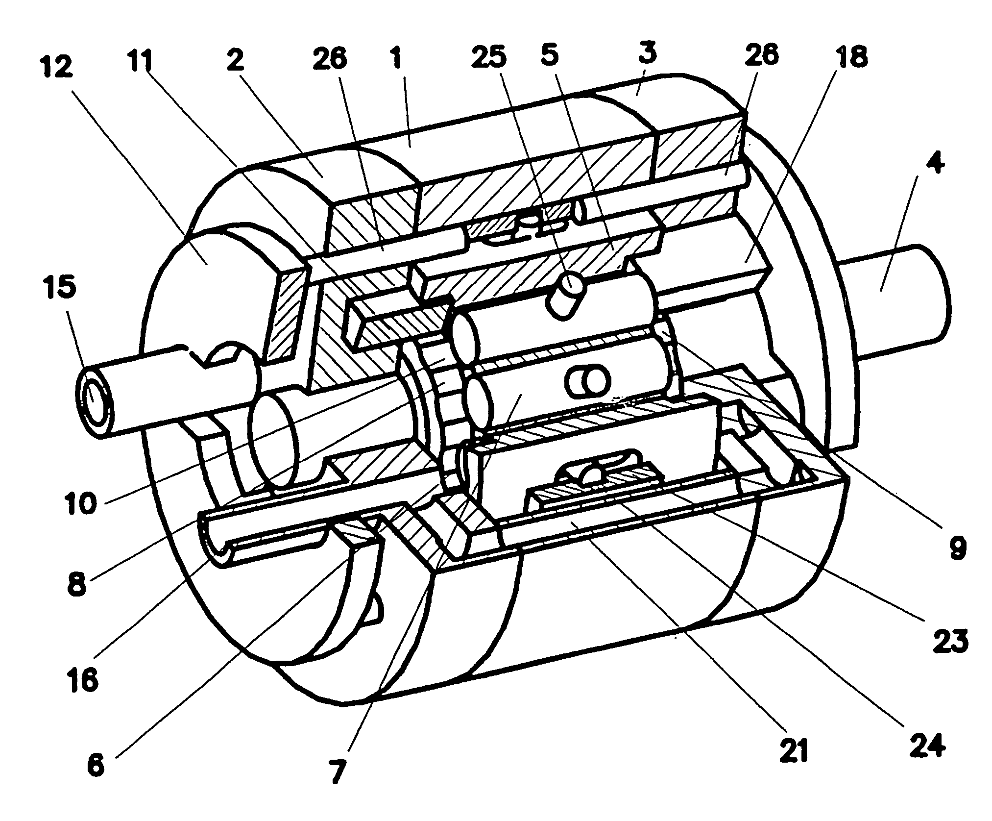
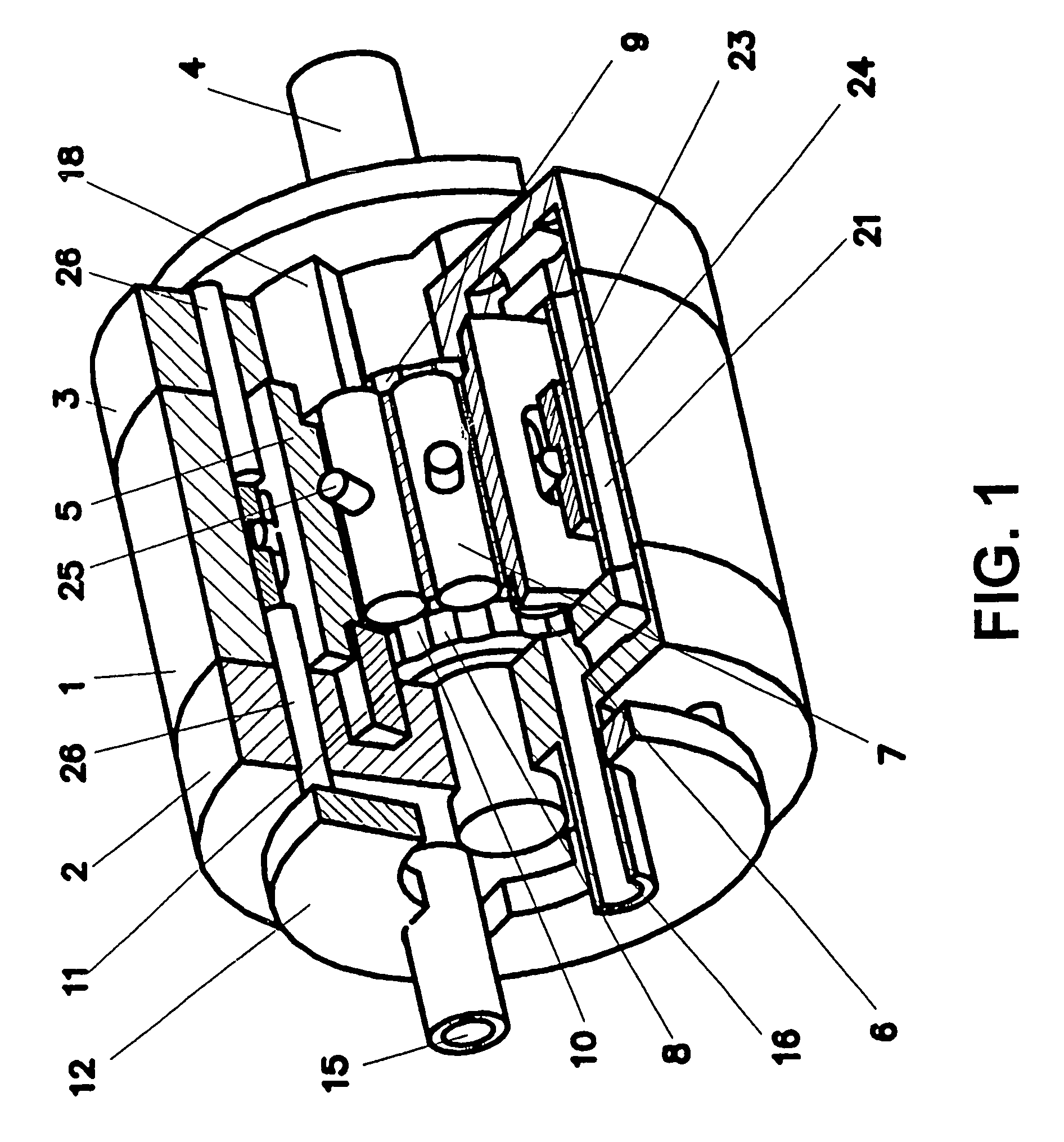
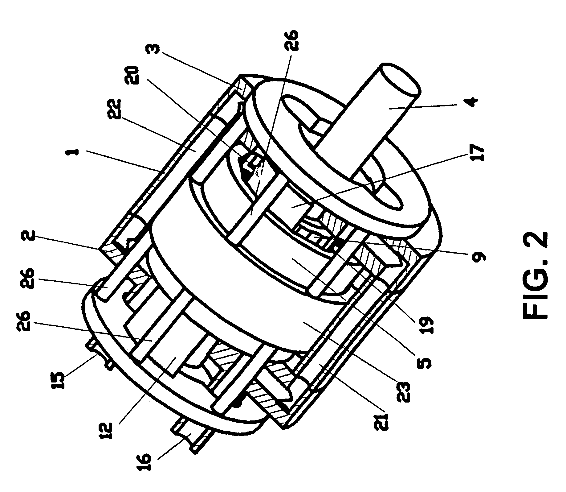
[0028]The rotary machine of the present invention embodiment (FIG. 1) comprises of housing (stator) 1 with end closures 2 and 3. Rotor 5 is mounted on shaft 4 within housing 1. Bores 6 are made through rotor 5 wherein axially movable displacers 7 are located.

[0029]The flank of rotor 5 which is opposite end closure 2 and called the first flank of rotor 5 has annular groove 8 passed through bores 6. Also the flank of rotor 5 opposite end closure 3 has a similar annular groove 9 which is made so that it passes through bores 6 as well. The annular grooves 8 and 9 are made so that bores 6 form recesses 10 in their inner cylindrical surfaces. The rotor machine comprises partition 11 mounted on end closure 2 opposite the first flank of rotor 5 and axially movable regulating member 12 mounted on the same end closure 2 opposite the same flank of rotor 5. The flank of partition 11 is in sliding contact with the bottom of annular groove 8.

[0030]This annular groove 8 together with end closure 2...


PUM


Abstract

The invention can be used for reversible pulsationless rotor high-pressure machines which can operate in pump and in motor mode. The inventive machine comprises a working chamber and an additional working chamber, separating jumpers and regulating elements. Said regulating elements are connected to each other with the aid of a kinematic link in such a way that the motion of one regulating element initiates the motion of another regulating element. Working cavity of said working chambers are arranged in an axial direction oppositely to each other and connected to each other by means of channels. A mechanism setting an axial relative position of displacers is embodied in such a way that it always provides a sliding contact of at least one displacer with each regulating element. Said invention makes it possible to extent the functional capabilities of similar rotor machines and improve the operational parameters thereof.

Description

[0001]This invention relates to mechanical engineering and may be used in high-pressure low pulsation reversible machines, able to operate both as a motor and a pump. Gaseous and liquid working fluids are applicable.[0002]In known adjustable rotary machine (UK 2207953), the rotor is mounted within the housing containing inlet and outlet openings. The rotor has the slots containing radially sliding valves. The pump comprises of a mechanism for positioning the valves in the rotor slots, a working chamber, and a regulating member movable in radial direction.[0003]Taken as the closest prior-art a high-pressure low pulsations reversible adjustable pump (RU 2123602) comprises housing with inlet and outlet openings, and a rotor mounted inside the housing. The rotor has the slots for the valves which are able to reciprocate along the rotor rotation axis. (Further, instead of the term “valve” the more common one “displacer” will be used). The pump comprises mechanism mounted in the housing p...

Claims


Application Information

Patent Timeline
IPC IPC(8): F04B43/12
CPCF01C1/3448F04B43/12
Inventor STROGANOV, ALEXANDR ANATOIEVICHVOLKOV, YURY MIKHAILOVICH
Owner STROGANOV ALEXANDR ANATOIEVICH
Features
  • R&D
  • Intellectual Property
  • Life Sciences
  • Materials
  • Tech Scout
  • Unparalleled Data Quality
  • Higher Quality Content
  • 60% Fewer Hallucinations
Learn More