Light field information coupler

A coupler and field information technology, which is applied in optics, instruments, optical components, etc., can solve the problems of coded beams affected by stray light and limited aperture of light field coding area, so as to facilitate continuous processing and utilization, improve quality and Encoding effect, effect of strong adaptability

Pending Publication Date: 2020-12-25
CHANGCHUN INST OF OPTICS FINE MECHANICS & PHYSICS CHINESE ACAD OF SCI
View PDF0 Cites 0 Cited by
  • Summary
  • Abstract
  • Description
  • Claims
  • Application Information

AI Technical Summary

Problems solved by technology

[0007] The present invention provides a light field information coupler for computational optical beam coding regulation in order to solve the problem that the aperture of the light field coding area is limited and the coded beam is seriously affected by stray light in computational optics and optical detection

Method used


Image

  • Light field information coupler
  • Light field information coupler
  • Light field information coupler

Examples


Embodiment 1

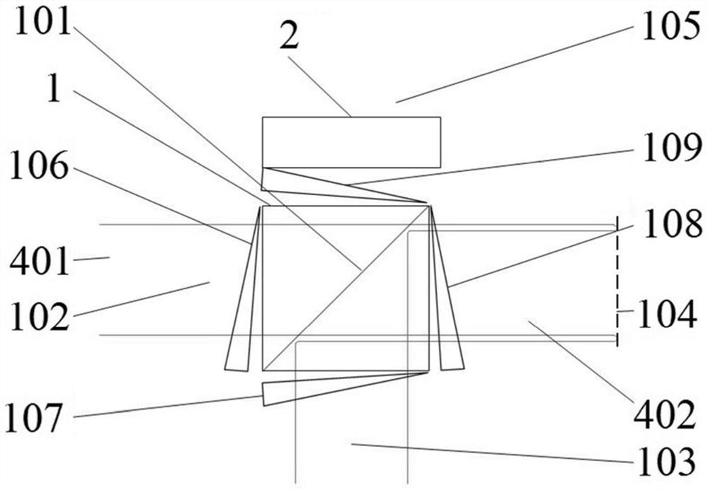
[0066] figure 1 The structure of the light field information coupler according to Embodiment 1 of the present invention is shown.

[0067] Such as figure 1 As shown, the light field information coupler provided by Embodiment 1 of the present invention includes: a beam splitter 1 and an optical trap 2, and the beam splitter 1 is a square prism, including a beam splitting surface 101, a beam incident end 102, a beam output end 103, and a beam encoding end 104 and optical trap end 105, the four surfaces of beam splitter 1 corresponding to beam incident end 102, beam exit end 103, beam coding end 104 and optical trap end 105 are respectively perpendicular to the respective beam directions, and the adjacent two surfaces perpendicular to each other.

[0068] The light beam incident end extinction reflection sheet 106 is arranged at the beam entrance end 102, the light beam exit end light emission end reflection sheet 107 is arranged at the beam exit end 103, the beam encoding end ...

Embodiment 2

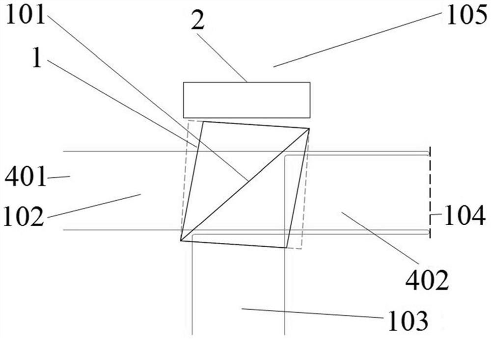
[0074] figure 2 The structure of the light field information coupler according to Embodiment 2 of the present invention is shown.

[0075] Such as figure 2 As shown, the light field information coupler provided by Embodiment 2 of the present invention includes: a beam splitter 1 and an optical trap 2, and the beam splitter 1 is a square prism, including a beam splitting surface 101, a beam incident end 102, a beam output end 103, and a beam encoding end 104 and optical trap end 105, the four surfaces of beam splitter 1 corresponding to beam incident end 102, beam exit end 103, beam encoding end 104, and optical trap end 105 are not perpendicular to the corresponding beam direction, and the adjacent two surfaces Not perpendicular to each other, the two surfaces of the beam splitter 1 corresponding to the beam incident end 102 and the beam encoding end 104 can be parallel or non-parallel, and the two surfaces of the beam splitter 1 corresponding to the beam output end 103 and...

Embodiment 3

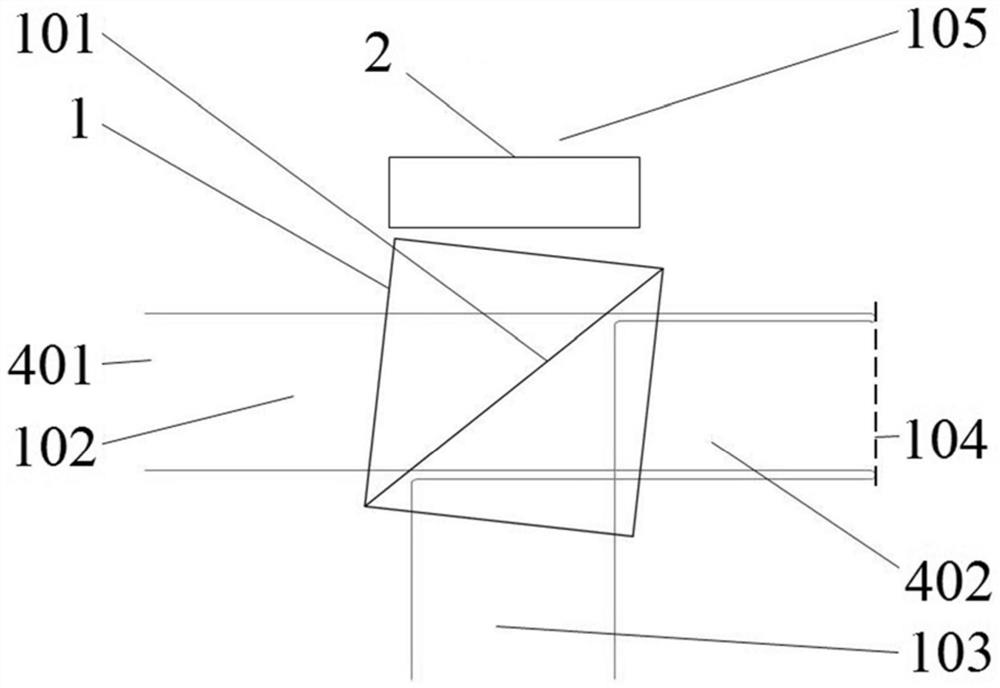
[0079] image 3 The structure of the light field information coupler according to Embodiment 3 of the present invention is shown.

[0080] Such as image 3 As shown, the light field information coupler provided by Embodiment 3 of the present invention includes: a beam splitter 1 and an optical trap 2, and the beam splitter 1 is a square prism, including a beam splitting surface 101, a beam incident end 102, a beam output end 103, and a beam encoding end 104 and optical trap end 105, the four surfaces of beam splitter 1 corresponding to beam incident end 102, beam exit end 103, beam encoding end 104, and optical trap end 105 are not perpendicular to the corresponding beam direction, and the adjacent two surfaces perpendicular to each other.

[0081] Since the beam incident end 102, the beam exit end 103, the beam encoding end 104, and the light trap end 105 of the beam splitter 1 are not perpendicular to the respective beam directions, the beam entrance end 102, the beam exit...


PUM


Abstract

The invention provides a light field information coupler. The coupler comprises a light splitting element and a light trap, wherein the light splitting element comprises a light splitting surface, a light beam incident end, a light beam emergent end, a light beam coding end and a light trap end, a light beam to be coded enters the light splitting element from the light beam incident end and is divided into two paths through the light splitting surface, one path is turned and then emitted to the light trap from the light trap end for extinction, and the other path is emitted from the light beamcoding end, is converted into a coded light beam after light field coding, is reflected back to the light splitting element, and is emitted from the light beam emergent end after being turned back bythe light splitting surface. By arranging the light trap, the light energy which does not participate in normal coding output is absorbed, and the influence of the energy on the output coding light beam in a stray light form is eliminated. In addition, an extinction reflector plate, an antireflection film and other structures are added to an optical splitter, and the small inclination angle design of the optical surface is carried out, so that the multiple reflected light of the optical surface deviates from the coding light path, and the influence of the multiple reflected light on the coding light beam in a stray light form is significantly reduced.

Description

technical field [0001] The invention relates to the technical field of beam coding and light field modulation, in particular to a light field information coupler for calculating optical beam coding and regulation. Background technique [0002] Computational optics technology is an emerging cross-technical research field integrating theories of geometric optics, physical optics, information optics, computational imaging, modern signal processing, and biomedical photonics. By applying the idea of ​​computer information processing, combining optical system modulation with back-end signal processing algorithms, computational optics can make information invisible under traditional lighting, imaging and other optical means visible, or greatly enhance the performance of the instrument, providing far beyond Traditional imaging techniques and the unprecedented perception of human vision (such as resolution, depth of field, field of view, information dimension and dynamic range). As ...

Claims


Application Information

Patent Timeline
Patent Type & Authority Applications(China)
IPC IPC(8): G01D5/26G02B27/10G02B27/00
CPCG01D5/26G02B27/00G02B27/10
Inventor 孙阳
Owner CHANGCHUN INST OF OPTICS FINE MECHANICS & PHYSICS CHINESE ACAD OF SCI
Why Eureka
Try Eureka