Stereoscopic display apparatus

Active Publication Date: 2014-02-06
JAPAN DISPLAY INC
View PDF4 Cites 6 Cited by
  • Summary
  • Abstract
  • Description
  • Claims
  • Application Information

AI Technical Summary

Benefits of technology

[0019]According to the present invention, it is possible to move the position of viewpoint, not only to the left and the right, but also into the

Problems solved by technology

However, although the position of the viewpoint from where the 3D image can be seen can be moved to the left or the right, with resp

Method used


Image

  • Stereoscopic display apparatus
  • Stereoscopic display apparatus
  • Stereoscopic display apparatus

Examples


Example

First Embodiment

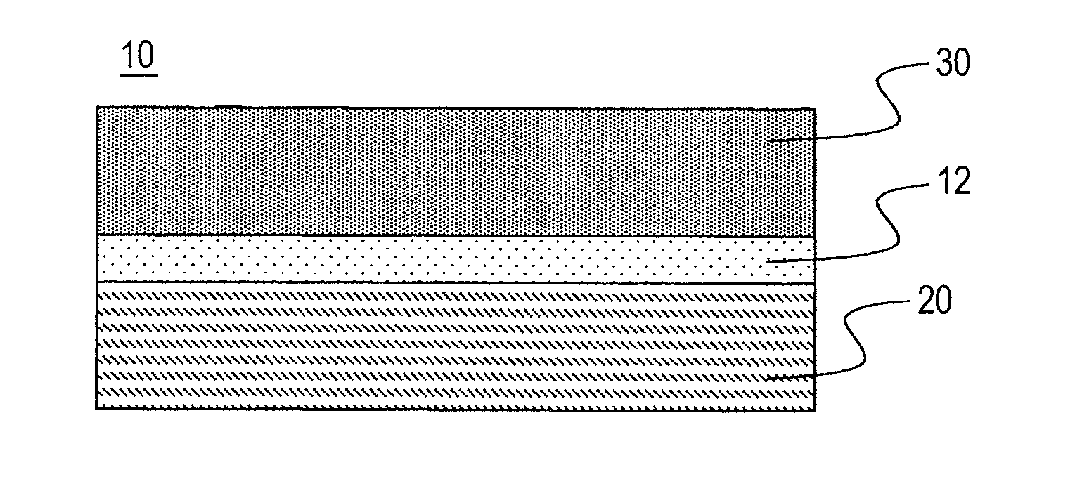
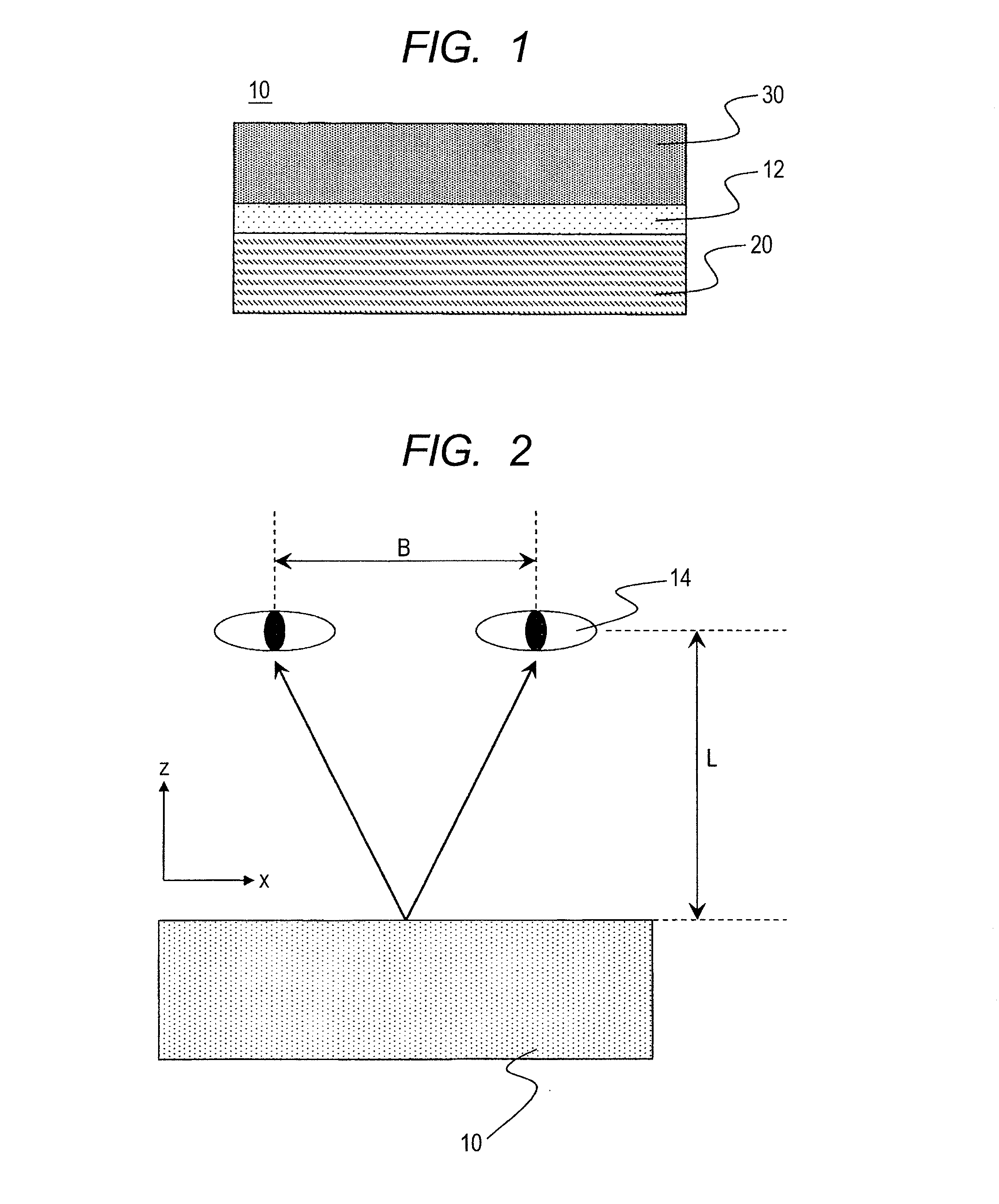
[0044]FIG. 1 shows an outline cross-section view of the stereoscopic display panel, according to an embodiment 1 of the present invention. The stereoscopic display panel 10 is made up with a display element 20 and a liquid crystal lens 30, wherein the display element 20 and the liquid crystal lens 30 are bonded by a bonding material 12. As the display element 20 may be applied a liquid crystal display (LCD) element, preferably, and may be applied a liquid crystal display element of an IPS (In-Plane Switching) method, for example. As the display element may be applied a display element, applying an organic EL therein, or other display element(s) than that. However, since it is necessary to enter a linearly polarized light upon the liquid crystal lens 30, a polarization plate or a phase difference plate may be provided, preferably, between the display element 20 and the liquid crystal lens 30, in particular, in case of that other than the liquid crystal display element...

Example

Second Embodiment

[0069]The stereoscopic display apparatus, according to an embodiment 2, will be explained by referring to FIGS. 9A to 10.

[0070]FIGS. 9A to 9C show cross-section views of the liquid crystal lens, according to the present embodiment. A first electrode is made from the transparent electrode, and a second electrode is made from the comb-like transparent electrode, respectively. And, a distance from a dotted line to a dotted line in the figure presents one pitch of the lens.

[0071]For example, as is shown in FIG. 9A, with applying the highest voltage on the second electrode (on) at a predetermined pitch, while applying the most suitable voltage lower than that or zero Volt on the other second electrode, it is possible to obtain such a preferable distribution of refractive index, as is shown in the figure. Herein, the distribution of refractive index means one obtained through averaging the refractive indexes in the z-direction at a certain position. It is already known th...

Example

Third Embodiment

[0075]Explanation will be made on the stereoscopic display apparatus, according to an embodiment 3 of the present invention, by referring to FIGS. 11A and 11B, and 12A and 12B.

[0076]In the embodiment 3, a small lens is formed within the lens pitch of the liquid crystal lens. In case where the viewpoint is at the central position thereof, the distribution of refractive index is brought to be as shown in FIG. 11A, for enabling to obtain a small lens effect. With doing this, it is possible to obtain a 3D view in the vicinity of a center of the panel, at the most appropriate viewing position, which is determined by the equation (Eq. 2).

[0077]On the other hand, as is shown in FIG. 11B, through shifting a small distribution of refractive index, little by little, within the lens pitch, it is possible to make up the condition of such characteristic curve (3), as shown in FIG. 6, without changing the lens pitch. As a result of this, it is possible to move the most appropriate...


PUM


Abstract

To provide a stereoscopic display apparatus, enabling to move the position of a viewpoint, not only left/right, but also in front/back directions, and to widen a range from where a 3D image can be seen. A stereoscopic display apparatus, with applying a stereoscopic display panel therein, comprising: a display element, which is configured to display parallax images for a left-side eye and a right-side eye, simultaneously; and a liquid crystal lens, which is attached onto the display element and configured to adjust a direction of a light emitting from the display element, further comprises an observer position detecting means and a liquid crystal lens driving means, wherein the liquid crystal lens driving means changes the pitch of a pattern of voltage to be applied onto plural numbers of electrodes of the liquid crystal lens, depending on the position of the observer, which is detected by the observer position detecting means.

Description

CLAIM OF PRIORITY[0001]This application claims priority from Japanese patent application JP2012-171211 filed on Aug. 1, 2012, the content of which is incorporated by reference into this application.BACKGROUND OF THE INVENTION[0002]1. Field of the Related Art[0003]The present invention relates to a stereoscopic display apparatus of naked-eye type, for enabling to display a 3D image, without applying special glasses.[0004]2. Description of the Related Art[0005]The stereoscopic display apparatuses can be classified, roughly, into a one applying the glasses, presenting pictures differing from each other to eyes on the left and right sides, and the other for giving a stereoscopic effect to the naked eyes as they are, without using the glasses. In the stereoscopic display apparatus of the naked-eye type without using the glasses, having the structure for entering lights to the left and right-side eyes, separately, there are proposed ones of applying therein parallax barriers and lenticula...

Claims


Application Information

Patent Timeline
IPC IPC(8): G02B27/22G02B30/25
CPCG02B27/2214G02B26/0875H04N13/305H04N13/373G02B26/08G02B30/27
Inventor OKA, SHINICHIROKOMURA, SHINICHI
Owner JAPAN DISPLAY INC
Why Eureka
Try Eureka