Parallel-connected inverters with separate controllers having impedance current regulators

a technology of impedance current regulator and parallel connection inverter, which is applied in the direction of emergency power supply arrangement, reactive power compensation, instruments, etc., can solve the problems of loss of load, problems that can arise, and the control system is not generally applicable to large or dispersed systems

Inactive Publication Date: 2006-12-05
WEG ELECTRIC CORP
View PDF17 Cites 65 Cited by
  • Summary
  • Abstract
  • Description
  • Claims
  • Application Information

AI Technical Summary

Problems solved by technology

In this system, a single inverter failure will cause loss of load.
When all of these characteristics are not present, problems can arise.
However, these control systems are not generally applicable for large or disperse systems.
In addition, the high speed communication needed between inverters in parallel causes a single point failure issue for parallel redundant power systems and thus makes the master / slave method less reliable.
Unfortunately, these systems are not believed to share current harmonics and transients, nor do these apparently share reactive current.

Method used


Image

  • Parallel-connected inverters with separate controllers having impedance current regulators
  • Parallel-connected inverters with separate controllers having impedance current regulators
  • Parallel-connected inverters with separate controllers having impedance current regulators

Examples


Embodiment Construction

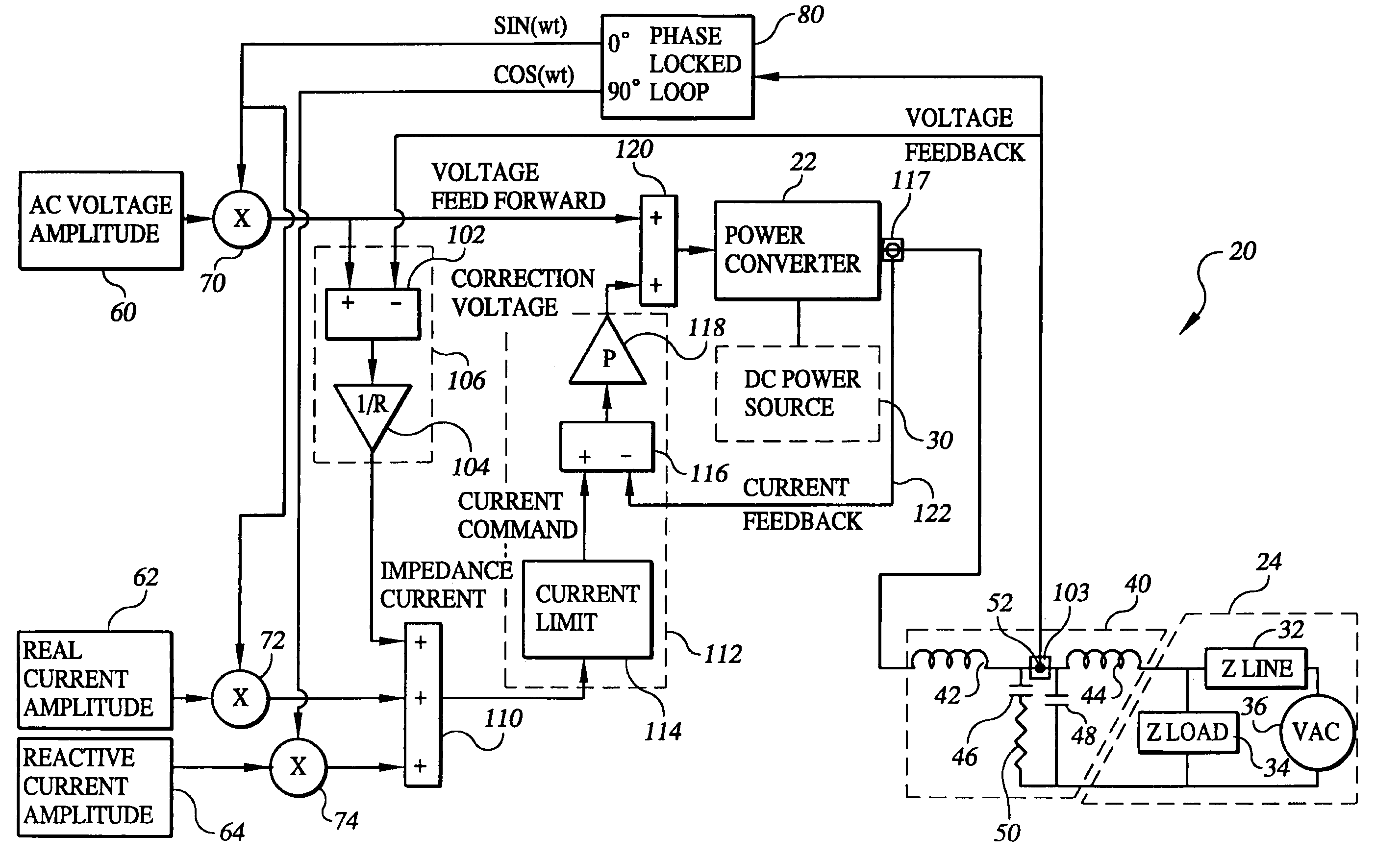
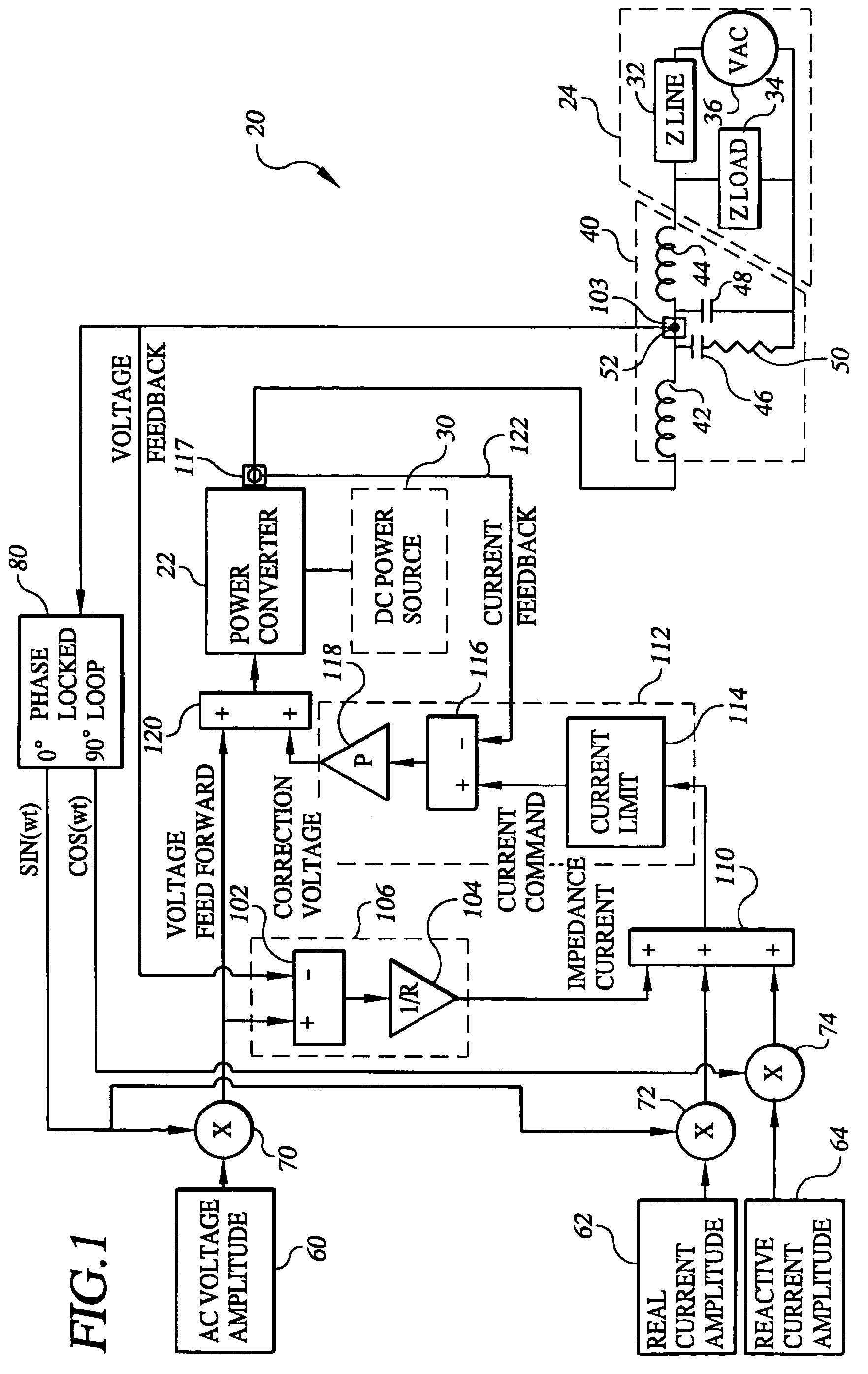
[0029]Referring to FIG. 1, the present invention is a system 20 designed for connecting a power converter 22 to an AC power network 24, and for controlling the power converter. The invention makes it possible to connect any number of power converter's 22 in parallel to the same AC power network 24 without the need for a separate control system connected to the multiple power converters 22. AC power network 24 can be a conventional utility grid or an isolated power network. System 20 works for both single and three-phase systems.

[0030]System 20 is connected between a DC power source 30, such as a battery, flywheel, photovoltaic panel, or fuel cell, and AC power network 24. In particular, DC power source 30 is connected so that the power it generates is provided to power converter 22.

[0031]Power converter 22 may comprise any conventional converter for converting DC power to AC power, e.g., converters of the type described in U.S. Pat. Nos. 2,821,639 and 5,191,519, which are incorporat...


PUM


Abstract

A control system (20) for a power converter (22) designed to convert DC power from a source (30) such as a battery, flywheel or fuel cell into AC power. The control system includes an impedance current regulator (106) for providing an impedance current signal to a summing unit (110) where it may be combined with real and reactive current command signals provided from respective sources (62, 64). The resultant current signal provided by the summing unit is provided to a voltage correction unit (112) that uses the resultant current signal in developing a correction voltage signal provided to the power converter. The correction voltage signal contains information used by the power converter in adjusting the real and reactive currents in its output AC power based on the ability of the AC power network to accept changes in current. Multiple power converters having the control system of the present invention may be connected in parallel to a single AC load or multiple AC loads, without the need for a separate control system interconnecting the power converters. The control system may be advantageously incorporated into a distributed generation network and in uninterruptible power systems, whether or not such systems are included in a distributed generation network.

Description

PRIOR APPLICATION INFORMATION[0001]This application is a continuation of application Ser. No. 10 / 200,916, filed Jul. 23, 2002, now U.S. Pat. No. 6,693,409, which claims the benefit of provisional application Ser. No. 60 / 307,568, filed Jul. 23, 2001.BACKGROUND OF THE INVENTION[0002]There are many types of new distributed generation (DG) and energy storage products being developed throughout the world. These include: fuel cells, flywheels, advanced batteries, micro-turbines, Stirling engines, wind turbines, solar cells and double layer capacitors. Each one of these devices requires a power electronic inverter at its output to make useful AC power. Typically, this is 50 or 60 Hz single or three-phase power.[0003]A number of techniques have been described in patents and literature for connecting these devices to each other and to a utility grid. All of these are techniques involve the use of parallel power converters. These converters fall into two categories, devices paralleled on the ...

Claims


Application Information

Patent Timeline
Patent Type & Authority Patents(United States)
IPC IPC(8): H02J7/00H02J3/18H02J3/38H02J9/06
CPCH02J3/18H02J3/387H02M7/40H02J3/383H02J3/386H02J3/24Y02B90/14H02J9/062H02J2001/004H02M2001/0025Y02E40/30Y02E10/563Y02E10/566Y02E10/763Y02B10/72Y02P90/40H02J2300/30H02J2300/24H02J3/381Y02B90/10Y02E10/56Y02E10/76H02M1/0025Y02B10/70
Inventor LYNCH, JONATHAN A.PETTER, JEFFREY K
Owner WEG ELECTRIC CORP
Why Eureka
Try Eureka