
Apparatus for controlling a boosted voltage and method of controlling a boosted voltage

a technology of boosted voltage and apparatus, which is applied in the direction of process and machine control, pulse technique, instruments, etc., can solve the problem of large ripple voltage of boosted voltage produced by these apparatuses, and achieve the effect of stable voltage level and reduced rippl

Active Publication Date: 2006-12-05
SAMSUNG ELECTRONICS CO LTD
View PDF13 Cites 2 Cited by
  • Summary
  • Abstract
  • Description
  • Claims
  • Application Information

AI Technical Summary

Benefits of technology

The present invention provides a method and apparatus for controlling a boosted voltage. The method involves generating the boosted voltage from an input voltage based on a control current, which is generated based on the boosted voltage. The apparatus includes a voltage generating circuit and a control circuit. The voltage generating circuit generates the boosted voltage from the input voltage using first, second, third, and fourth switches. The control circuit generates the control current based on the boosted voltage. The technical effect of the invention is to provide a stable voltage level for the boosted voltage with reduced ripple.

Problems solved by technology

However, the boosted voltages produced by these apparatuses have a large ripple voltage when a large load current flows through the load.

Method used


Image

  • Apparatus for controlling a boosted voltage and method of controlling a boosted voltage
  • Apparatus for controlling a boosted voltage and method of controlling a boosted voltage
  • Apparatus for controlling a boosted voltage and method of controlling a boosted voltage

Examples


Embodiment Construction

[0021]Hereinafter the exemplary embodiment of the present invention will be described in detail with reference to the accompanying drawings.

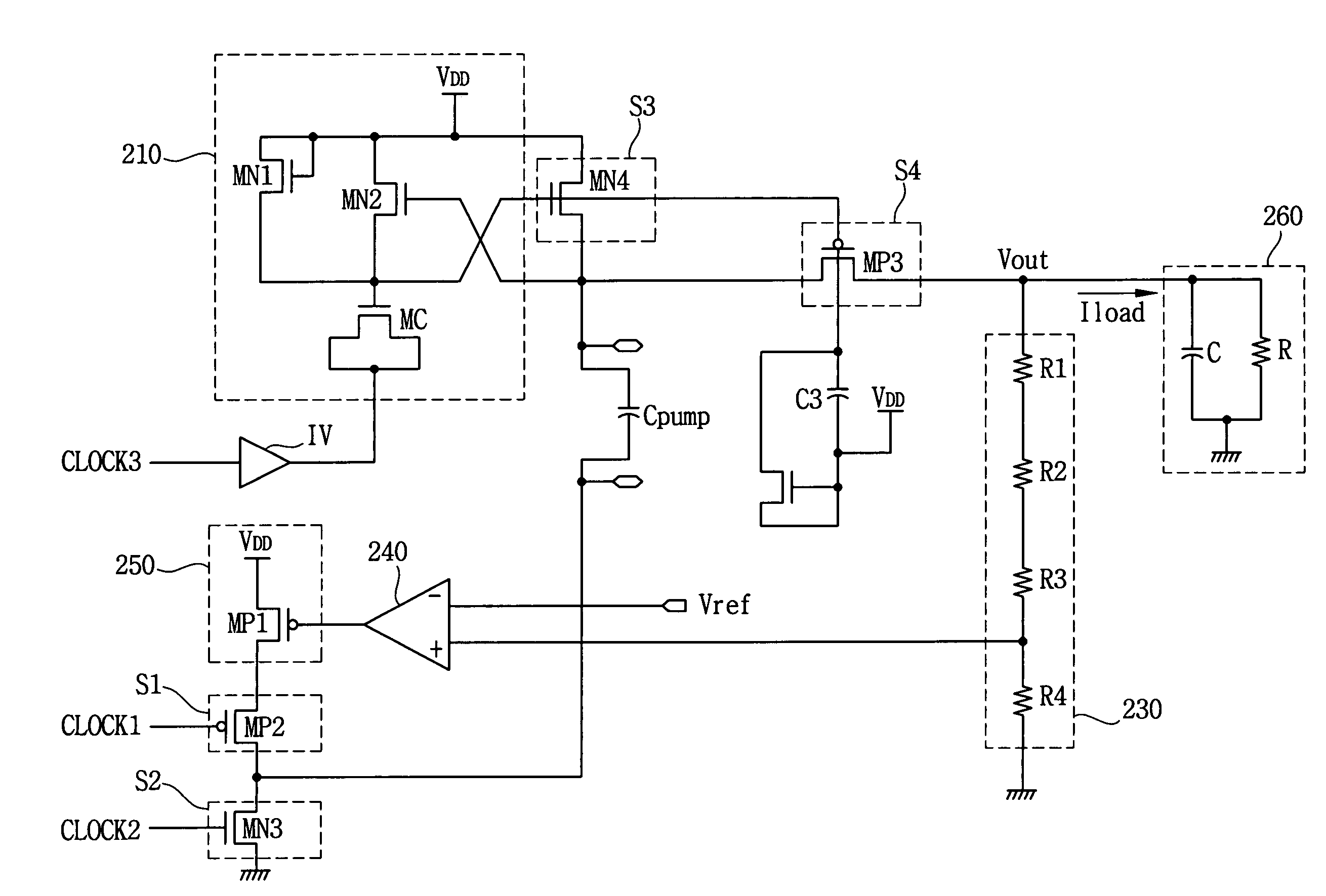
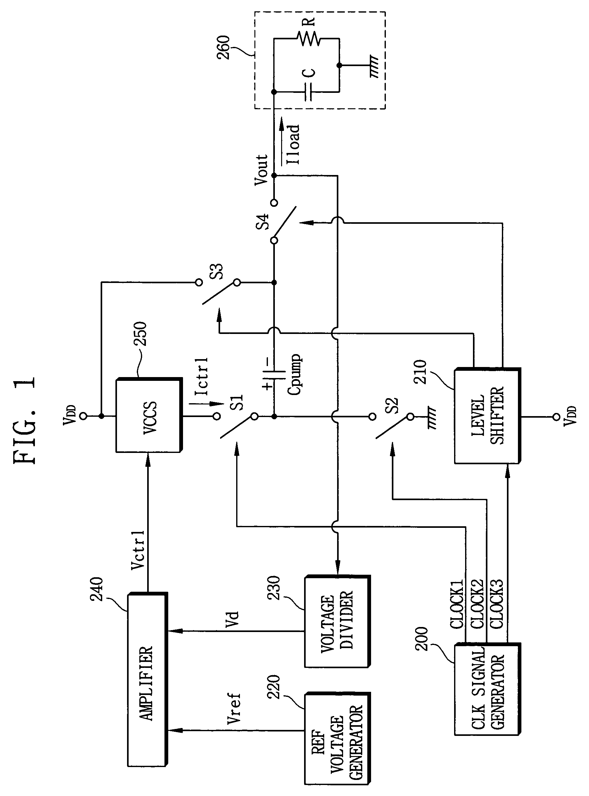
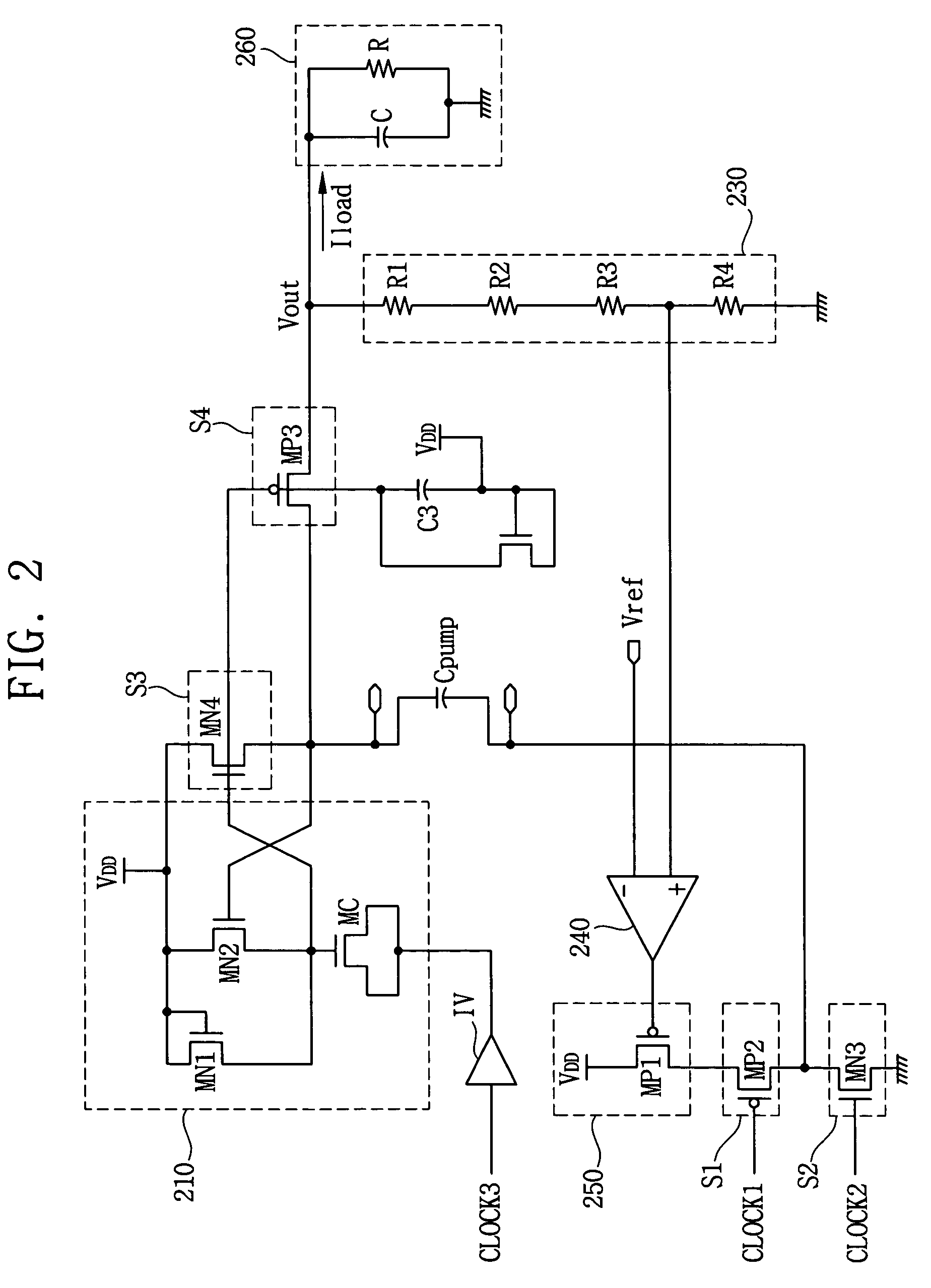
[0022]FIG. 1 is a block diagram showing an apparatus for controlling a boosted voltage according to one exemplary embodiment of the present invention, and FIG. 2 is an exemplary circuit level diagram of the apparatus shown in FIG. 1.

[0023]Referring to FIGS. 1 and 2, the apparatus for controlling the boosted voltage includes a clock signal generator 200, a level shifter 210, first and second switches S1 and S2, third and fourth switches S3 and S4 and a capacitor Cpump forming a voltage generating circuit generating a boosted voltage (Vout) from an input voltage (VDD) based on a control current (Ictrl). The apparatus further includes a reference signal generator 220, a voltage divider 230, an amplifier 240, and a voltage controlled current source (VCCS) 250 forming a control circuit generating the control current Ictrl.

[0024]The clock signal gener...


PUM


Abstract

The apparatus for controlling a boosted voltage includes a voltage generating circuit and a control circuit. The voltage generating circuit is configured to generate a boosted voltage from an input voltage based on a control current, and the control circuit is configured to generate the control current based on the boosted voltage.

Description

CROSS-REFERENCE TO RELATED APPLICATIONS[0001]This application relies for priority upon Korean Patent Application No. 2003-55744 filed on Aug. 12, 2003, the contents of which are herein incorporated by reference in their entirety.BACKGROUND OF THE INVENTION[0002]1. Field of the Invention[0003]The present invention relates to an apparatus for controlling a boosted voltage and a method of controlling the boosted voltage.[0004]2. Description of the Related Art[0005]Portable electric devices are provided with a portable power supply such as a battery. The portable power supply usually has a voltage source lower than 3 volts.[0006]Electric devices coupled to the portable electric devices operate using a high voltage source, and thus require a device for boosting the voltage of the portable power supply to a fixed driving voltage.[0007]U.S. Pat. Nos. 6,534,963 and 6,445,623 both disclose conventional apparatuses for boosting voltage. However, the boosted voltages produced by these apparatu...

Claims


Application Information

Patent Timeline
Patent Type & Authority Patents(United States)
IPC IPC(8): G05F1/10G05F3/02H03K17/00H02M3/07H03K17/06
CPCH02M3/073H03K17/063H02M2001/0045H02M1/0045H03K17/00
Inventor SHIN, SOON-KYUN
Owner SAMSUNG ELECTRONICS CO LTD
Learn More