Autofocus method based on successive parameter adjustments for contrast optimization

a technology of contrast optimization and autofocus method, which is applied in the direction of reradiation, measurement devices, instruments, etc., can solve the problems of insufficient accuracy of motion compensation applied to each radar a/d sample, loss of estimated phase error accuracy, and limited map drift method

Active Publication Date: 2006-12-05
RAYTHEON CO
View PDF6 Cites 27 Cited by
  • Summary
  • Abstract
  • Description
  • Claims
  • Application Information

AI Technical Summary

Problems solved by technology

For certain applications the accuracy of the motion compensation applied to each radar A / D sample is insufficient.
However, as the order of the phase error increases, and the sub-apertures get smaller, the estimated phase error tends to lose accuracy because of the reduced Signal to Noise Ratio (SNR).
Because of this fundamental limitation, the Map Drift Method is limited to the case of low order corrections.
Because of the requirement of point like targets, PGA fails where there are no point like targets to be used with this method.
Both Map Drift and PGA methods lack metrics to determine the quality of the phase error estimates computed by each method.
However, the computational requirements of SSA is prohibitively intense for SAR data, thus impractical with current airborne computer technology.

Method used


Image

  • Autofocus method based on successive parameter adjustments for contrast optimization
  • Autofocus method based on successive parameter adjustments for contrast optimization
  • Autofocus method based on successive parameter adjustments for contrast optimization

Examples


Embodiment Construction

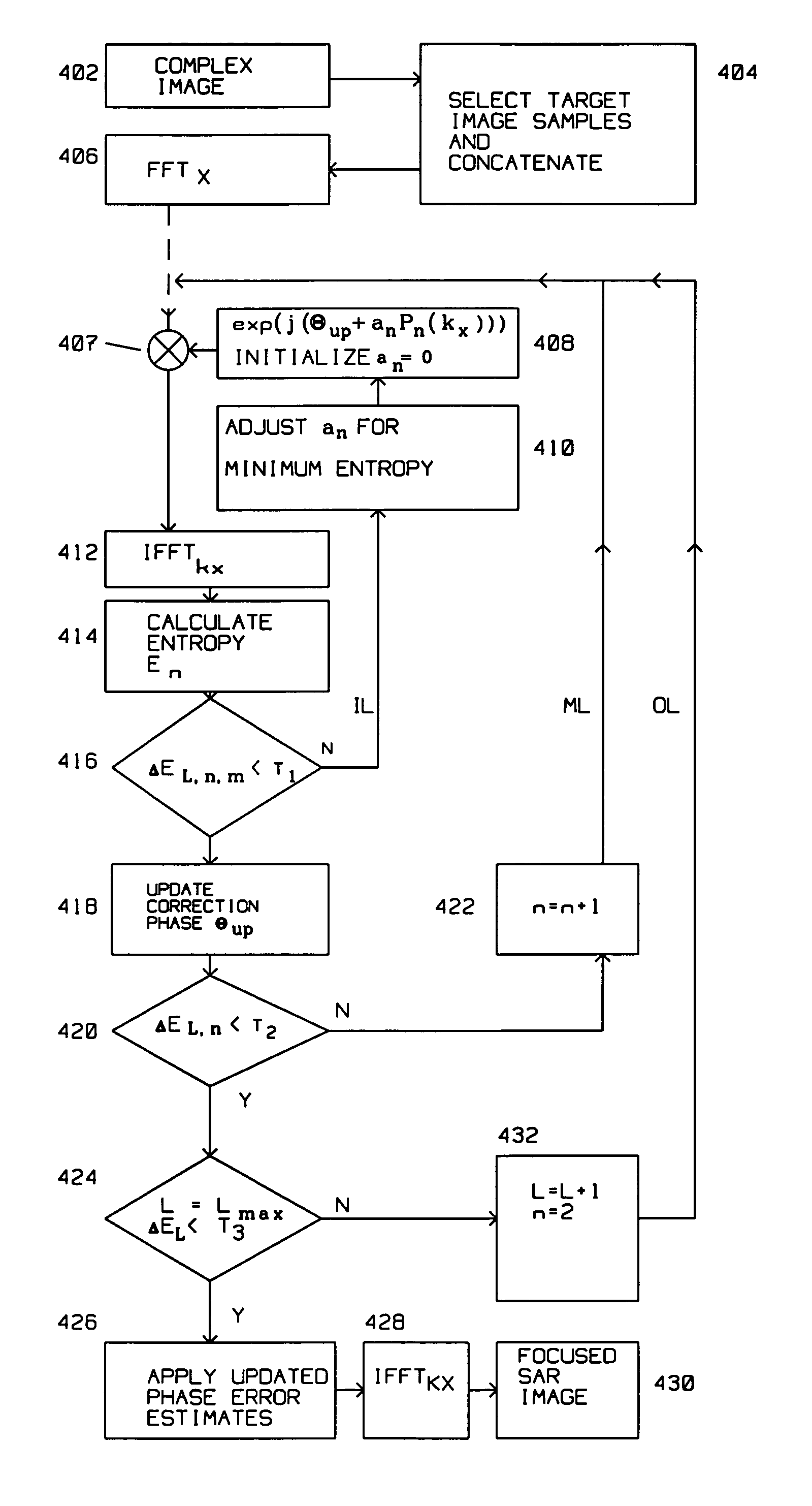
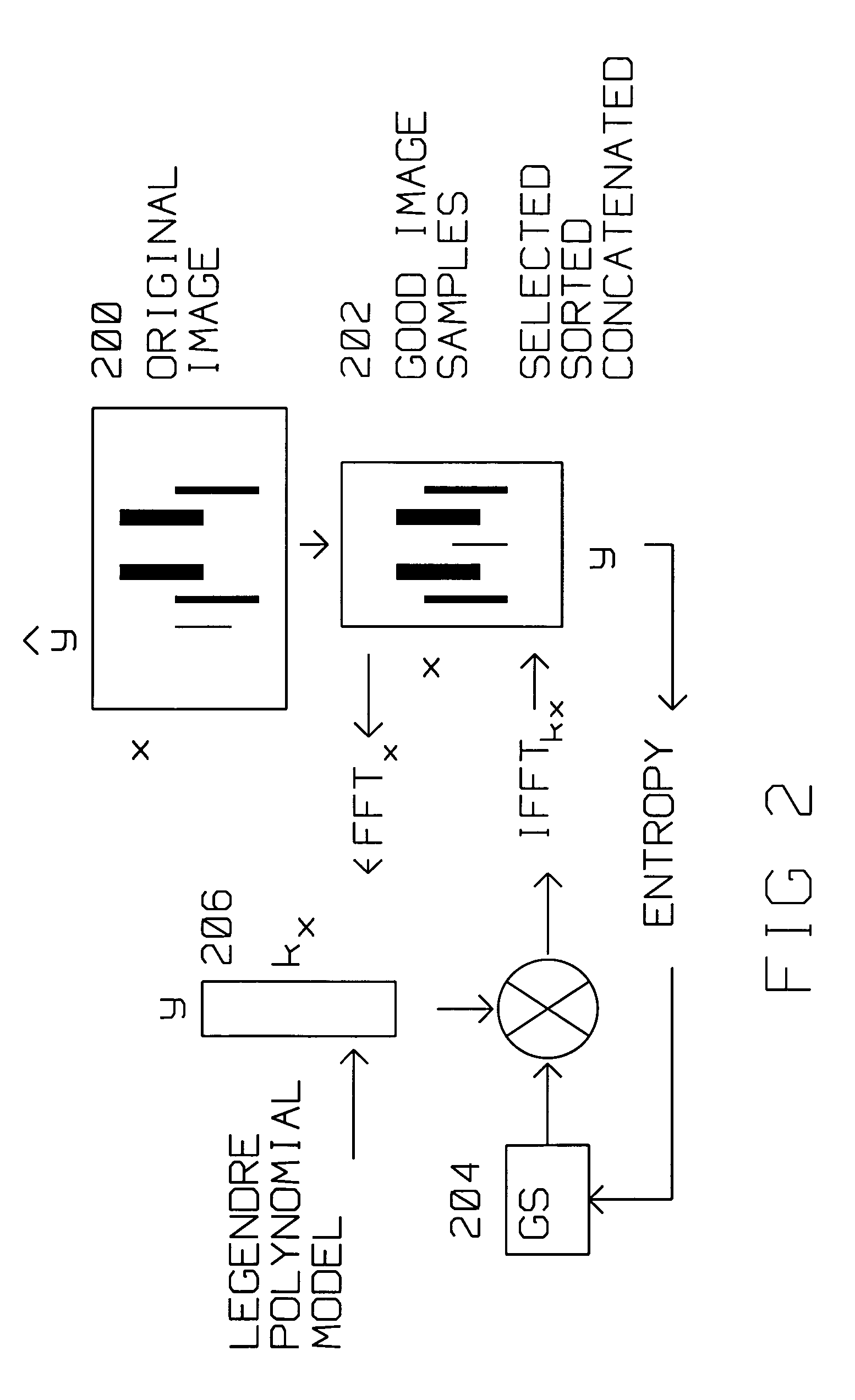
[0035]The present invention describes an autofocus method for SAR images, called successive parameter adjustment (SPA) based on successive search of parameters of an orthogonal (Legendre) polynomial for best SAR image contrast and sharpness. Unlike the prior art PGA method, SPA can be applied to a SAR scene without point like targets. Unlike SSA, SPA allows choosing a balance between computational requirements and performance by adjusting the number of test image samples, and tolerance to stop iterations. SPA is also applicable for the case of the spatially variant phase error that varies with target position because local image samples for image quality measurements can be selected with fewer constraints for the estimation of the phase error that varies with target position.

[0036]Another important feature of SPA is its applicability where there are pulse drops, i.e. missing pulses during an aperture (frame) forming a SAR image. This flexibility is because SPA is based on fitting ph...


PUM


Abstract

A radar on a moving platform generates an initial synthetic aperture (SAR) image of a scene from a sequence of periodic pulse returns approximately motion compensated. The SAR image is formed from pixel intensities zn(x,y) within a x,y extent of the initial synthetic aperture image. Targets are selected from the initial synthetic aperture image using a sliding window, computing a first entropy for the selected targets, and sorting the targets using the first entropy to obtain a target list having target elements, then concatenating the target elements to form a data matrix compatible in the azimuth dimension with a Fast Fourier Transform.A phase correction for autofocus is iteratively computed and applied to the initial synthetic aperture image using an inner loop, a mid loop and an outer loop. The phase correction is expressed using an orthogonal polynomial having a plurality n consecutive terms an, a2 denoting a quadratic term, and aN denoting a last order term. The outer loop, using an L index, calculates an outer loop EL(a2) entropy for the quadratic term and an outer loop EL(aN) entropy for the last order term. Iterations within the outer loop continue until EL(a2)−EL(aN) is less than an outer loop tolerance.Similarly, the mid loop, and inner loop continue until the computation of their respective entropies meet a pre-set tolerance. The inner loop entropy uses a Golden Section search for computing the inner loop entropy.

Description

[0001]This invention was made with Government support under Contract No. F19628-00-C-0100 awarded by the Department of the Air Force. The Government has certain rights in this invention.BACKGROUND OF THE INVENTION[0002]1. Field of Invention[0003]This invention is in the field of autofocus methods for Synthetic Aperture Radar (SAR) imaging.[0004]2. Description of the Related Art[0005]Synthetic Aperture Radar (SAR) radar is used for ground mapping as well as target identification. The general principle behind SAR is to coherently combine the amplitude and phase information of radar returns from a plurality of sequentially transmitted pulses. These pulses are from a relatively small antenna on a moving platform. As the platform moves, the information contained in the pulses is combined to arrive at a high resolution SAR image.[0006]The plurality of returns creating a SAR image generated by the transmitted pulses along a presumed known path of the platform make up a frame length. Theore...

Claims


Application Information

Patent Timeline
Patent Type & Authority Patents(United States)
IPC IPC(8): G01S13/90
CPCG01S13/90G01S13/9027G01S13/9019
Inventor CHO, KWANG M.HUI, LEO H.
Owner RAYTHEON CO
Why Eureka
Try Eureka