Stylus input device utilizing a permanent magnet

a permanent magnet and input device technology, applied in the field of input devices, can solve the problems of difficult stylus use, small writing area of the stylus, damage to the writing surface of the pda, etc., and achieve the effect of increasing the magnetic field strength

Inactive Publication Date: 2006-12-05
CIRQUE CORPORATION
View PDF30 Cites 51 Cited by
  • Summary
  • Abstract
  • Description
  • Claims
  • Application Information

AI Technical Summary

Benefits of technology

[0016]It is another object to provide a passive stylus that can provide “start” and “stop” writing signals to a display device, wherein the signals are actuated by normal writing movements and actions.
[0017]It is another object to provide a passive stylus that can include an inking cartridge that provides real inking of the stylus on paper when used off-screen.
[0018]It is another object to provide a passive stylus that can operate in three dimensions by providing a sufficient number of sensors to provide a three dimensional detection volume.
[0019]It is another object to provide a passive stylus that increases magnetic field strength to thereby function as an indicator of a changing signal.

Problems solved by technology

When a stylus requires pressure in order to be detectable, the writing surface of the PDA can be damaged.
In addition, the writing area for the stylus is typically very small.
It is also difficult to use a stylus when there is no visual feedback or “inking trail” to show the writer what has been written.
Inking can also be difficult if there is a delay between stylus movement and the appearance on a display screen of what is being written.
The prior art also fails to teach any type of stylus which can operate without making contact with a surface that can detect the presence of the stylus.
It is a tedious and time consuming task with state of the art input options on cell phones.

Method used


Image

  • Stylus input device utilizing a permanent magnet
  • Stylus input device utilizing a permanent magnet
  • Stylus input device utilizing a permanent magnet

Examples


Embodiment Construction

[0050]Reference will now be made to the drawings in which the various elements of the present invention will be given numerical designations and in which the invention will be discussed so as to enable one skilled in the art to make and use the invention. It is to be understood that the following description is only exemplary of the principles of the present invention, and should not be viewed as narrowing the claims which follow.

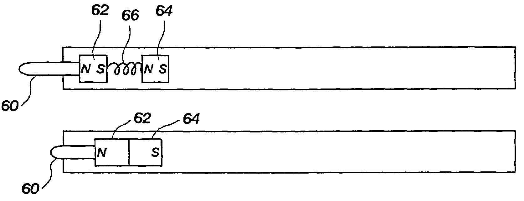
[0051]The presently preferred embodiment of the invention is a plurality of magnetic sensors that are capable of determining a location and orientation of a passive stylus that generates a magnetic field without using a power source. In the presently preferred embodiment, the plurality of magnetic sensors are directionally sensitive devices. For example, the magnetic sensors can be a magnetic field sensor such as one sold having part number KMZ51 from Philips Semiconductors. However, any similar magnetic sensor can be substituted and create the same results...


PUM


Abstract

A stylus that operates utilizing magnetic fields, wherein a permanent magnet is disposed within a passive stylus that is detectable by a plurality of magnetic sensors that remove the magnetic field of the stylus from the earth's relative magnetic field to thereby obtain vectors that are used in a triangulation equation to determine the location of the stylus in two or three dimensions, depending upon the number of magnetic sensors that are used, wherein one set of magnetic sensors can be used as a reference for earth's magnetic field, and wherein each of the magnetic sensors includes a polarizing coil to change direction of sensitivity, a null coil and a flipping coil.

Description

BACKGROUND[0001]1. The Field of the Invention[0002]This invention relates generally to input devices for electronic information devices. More specifically, the present invention provides a stylus that is operable in two or three dimensions, and which is utilized to provide input such as lines that represent movement of the stylus within a field of operation, or cursor control for computers and portable information appliances such as personal digital assistants (PDAs) or other types of electronic appliances such as mobile telephones.[0003]2. Background of the Invention[0004]The state of the art of input devices utilizing a stylus is generally characterized by digitizing tablets or a touchpad. A digitizing tablet is generally a large surface that is used to input data with a stylus that is coupled to the tablet or touchpad. For example, a cable connects the stylus to the tablet, and movement of the stylus is detected or tracked as it moves across the surface of the tablet. The movemen...

Claims


Application Information

Patent Timeline
Patent Type & Authority Patents(United States)
IPC IPC(8): G09G5/00G06F3/041G06F3/038G06F3/046
CPCG06F3/0346G06F3/0354G06F3/03545G06F3/0383G06F3/041G06F3/046G06F3/03
Inventor TAYLOR, BRIANLEE, DANIEL JOSEPHHARNEY, MICHAELGYORI, BENJAMIN JAZEF
Owner CIRQUE CORPORATION
Why Eureka
Try Eureka