Light scanning apparatus having a liquid crystal deflector and image forming apparatus using the same

a liquid crystal deflector and light scanning technology, applied in the field of light scanning apparatus, light scanning method, image forming apparatus, can solve the problems of affecting the quality of the image, so as to achieve the effect of forming a complex lens and a large scan line curvatur

Inactive Publication Date: 2006-12-05
RICOH KK
View PDF26 Cites 26 Cited by
  • Summary
  • Abstract
  • Description
  • Claims
  • Application Information

AI Technical Summary

Benefits of technology

[0064]The light scanning apparatus may further include a resin lens provided in the optical path from said light source to said scanned face. Since the optical properties of the resin lens depends on temperature and humidity, the position of light spot may change and increase the cu

Problems solved by technology

If the scan line pitch within an image varies in the sub scan directions, the image is distorted or the density of the image is not uniform.
The distortion of the image and the non-uniformity of the image density degrade the quality of the image substantially.
If the curvature of the scan lines is not uniform in a color image formed by a tandem type image forming apparatus, the curvature results in an unevenness in color, density, and hue.
Especially, if a resin lens is provided in the light path from the light source to the scanned face, the resin lens may deform due to changes in temperature and/or humidity.
The above methods effectively adjust the scan line pitch and compensate the scan line curvature, but inherit a side effect in that the adjustment of the light spot position also changes the light intensity of the light spot.
In the case that the liquid crystal element is used, a change in deflecting angle causes a change in the transmissivity of the liquid crystal element, and results in a change in the light intensity of the light spot.
In the case of the multi-beam scanning method, for example, if the light intensity of the light spots varies between the scan lines, especially the quality of half-tone images often degrades substantially.
This method has a limit in applicability due to the durability, noise, and vibration of a motor that rotates the polygon mirror and the limit in the modulation speed of the laser.
In the case of the semiconductor laser array, however, it is difficult to increase the number of channels due to the limitations of fabrication processes, to remove thermal and electrical crosstalk, and to shorten the wavelength of the light beam.
The cost of the semiconductor laser array is still high.
On th

Method used


Image

  • Light scanning apparatus having a liquid crystal deflector and image forming apparatus using the same
  • Light scanning apparatus having a liquid crystal deflector and image forming apparatus using the same
  • Light scanning apparatus having a liquid crystal deflector and image forming apparatus using the same

Examples


Embodiment Construction

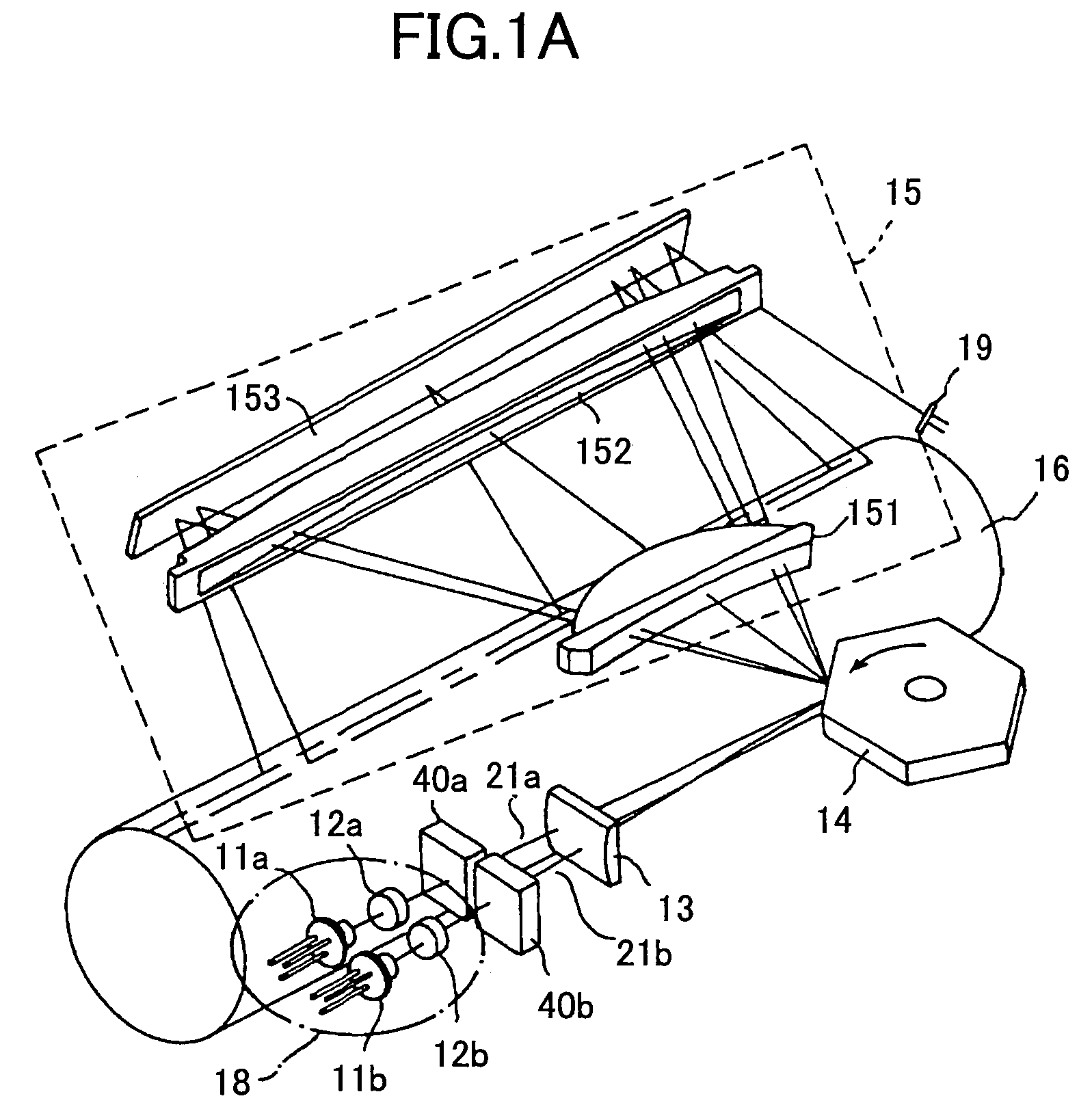
[0113]Preferred embodiments of the present invention will be described by reference to the drawings.

[0114]FIG. 1A is a schematic diagram showing a multi-beam light scanning apparatus according to an embodiment of the present invention.

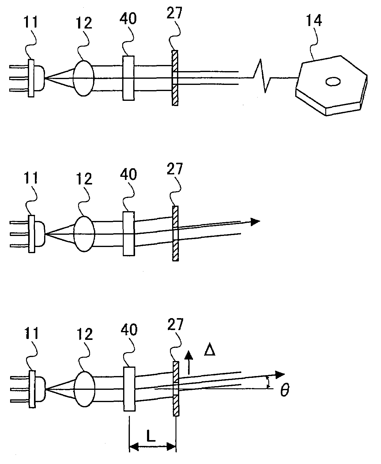
[0115]Semiconductor laser diodes 11a and 11b are provided as light sources, and each of them emits a diverging light beam. The light beams are transformed into parallel beams by coupling lenses 12a and 12b so that they fit the remaining optical system in this case. In another case, the light beams may be transformed into weakly diverging beams or weakly converging beams.

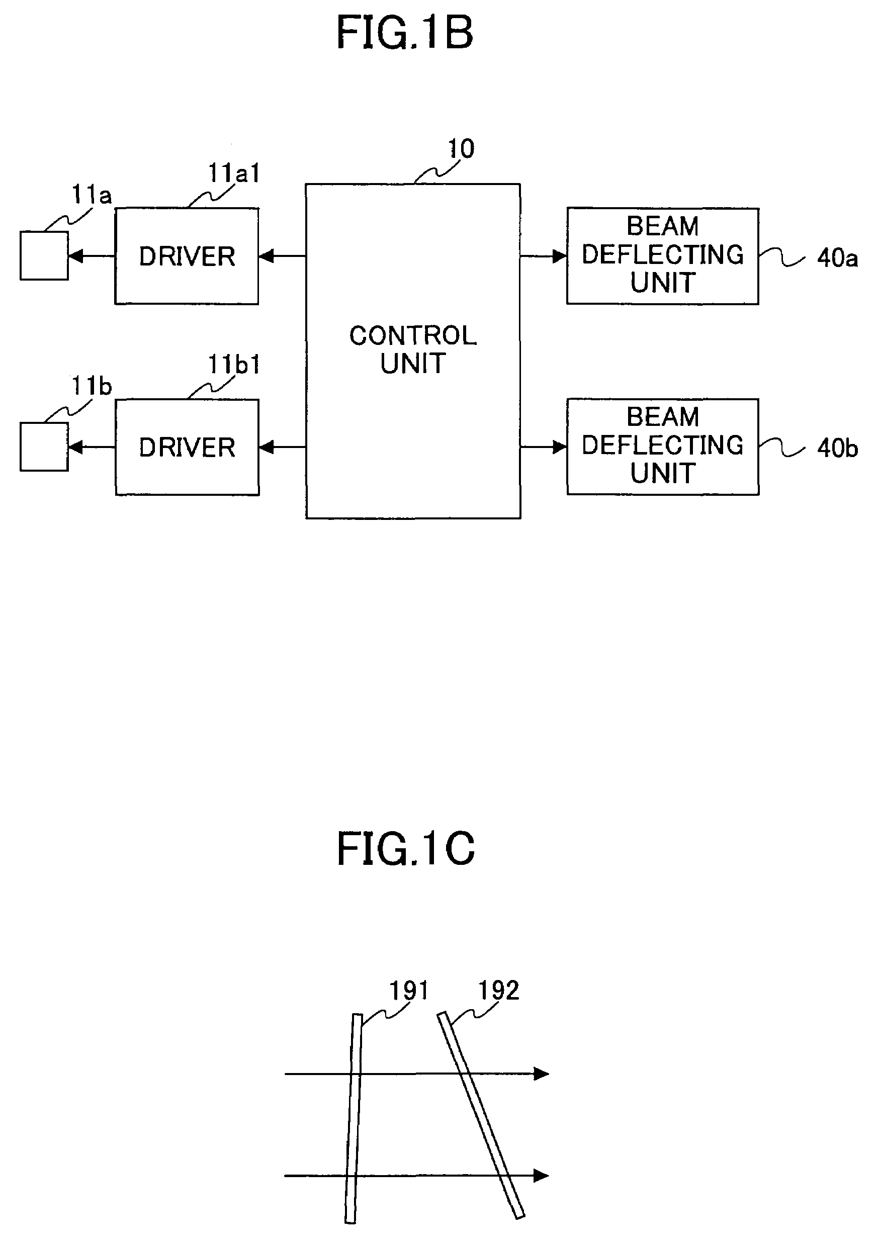
[0116]The light beams transformed by the coupling lenses 12a and 12b go through beam deflecting units 40a and 40b, respectively. The light beams are converged in the sub-scan directions by a cylindrical lens 13, and form long linear images in the main-scan directions on the deflecting reflective face of a polygon mirror 14. The linear image formed by one light beam is separated from the...


PUM


Abstract

A light scanning apparatus that scans a scanned face with a light beam includes an adjusting unit that adjusts the position of a light spot of the light beam formed on the scanned face, and a compensating unit that compensates the light intensity of the light beam at the scanned face due to change caused by the adjustment of the position of the light spot. Accordingly, the light scanning apparatus can reduce or eliminate the deviation in exposure between scan lines of the multi-beam scan method and the deviation in exposure between photosensitive bodies of the tandem type image forming apparatus.

Description

BACKGROUND OF THE INVENTION[0001]1. Field of the Invention[0002]The present invention generally relates to a light scanning apparatus, a light scanning method, and an image forming apparatus.[0003]The present invention relates more particularly to a light scanning apparatus (multi-beam scanning apparatus) that simultaneously scans a face (scanned face) with a plurality of light beams emitted by a light source(s), and to an image forming apparatus such as a laser printer, digital copier, a laser facsimile, and a laser plotter using the light scanning apparatus to write images.[0004]2. Description of the Related Art[0005]Light scanning apparatuses are used for laser printers, digital copiers, facsimile machines, and laser plotters, for example. The light scanning apparatus conventionally uses one light beam (single beam scanning method), but the light scanning apparatus that uses a plurality of light beams to simultaneously scan a single scanned face (multi beam scanning method) is be...

Claims


Application Information

Patent Timeline
IPC IPC(8): B41J27/00B41J2/47G02B26/12H04N1/047H04N1/113H04N1/12H04N1/191H04N1/40
CPCB41J2/473G02B26/123G02B26/127H04N1/0473H04N1/40006H04N1/40031H04N1/40037H04N1/4005H04N1/40056H04N1/1135H04N1/12H04N1/1911H04N2201/04765
Inventor AMADA, TAKUUEDA, TAKESHI
Owner RICOH KK
Why Eureka
Try Eureka