
Reflective display device using photonic crystals

Active Publication Date: 2006-12-05
SAMSUNG ELECTRONICS CO LTD
View PDF16 Cites 38 Cited by
  • Summary
  • Abstract
  • Description
  • Claims
  • Application Information

AI Technical Summary

Benefits of technology

[0010]In an effort to solve the above problems, it is a feature of an embodiment of the present invention to provide a reflective display device using photonic crystals as a reflective color filter that has a high reflection efficiency and a simplified structure.

Problems solved by technology

The color filter significantly affects the efficiency of the reflective display devices, since it passes only a portion of the incident white light.
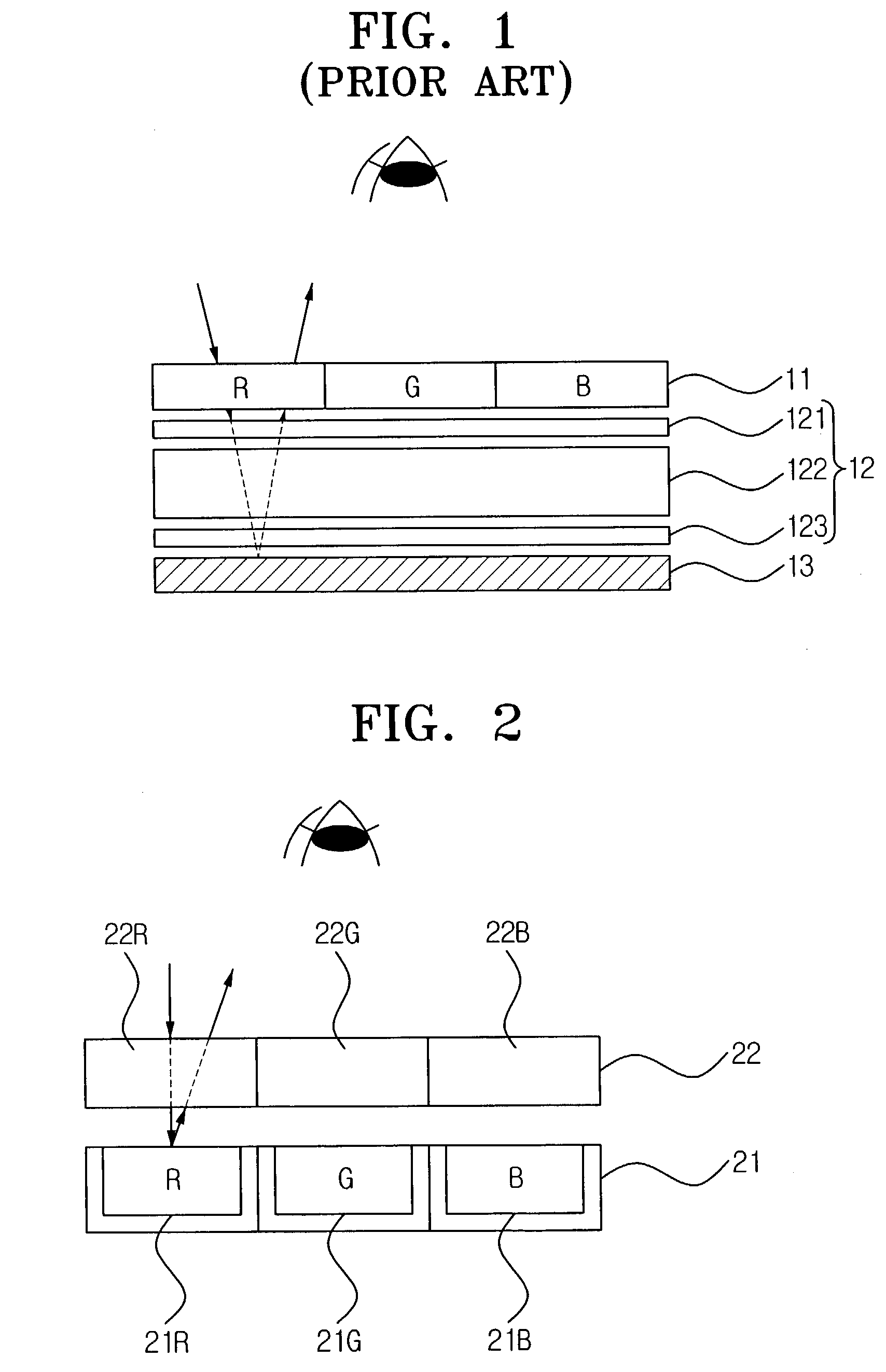
Such a conventional reflective display device has a problem in that light efficiency is reduced as the light passes through the transmission type color filter 11 twice, both upon entering and exiting the device.
In addition, it is also problematic that the luminance and contrast are low, and the hue and brightness are not vivid.

Method used


Image

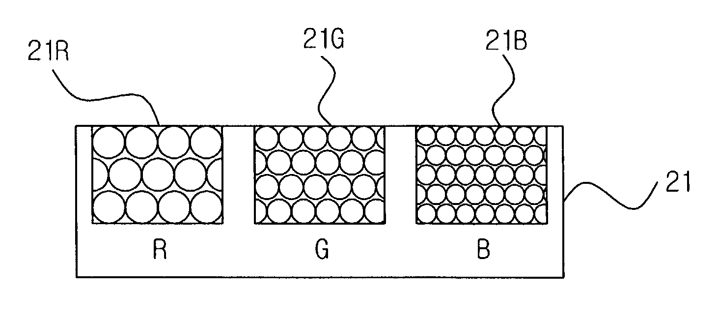
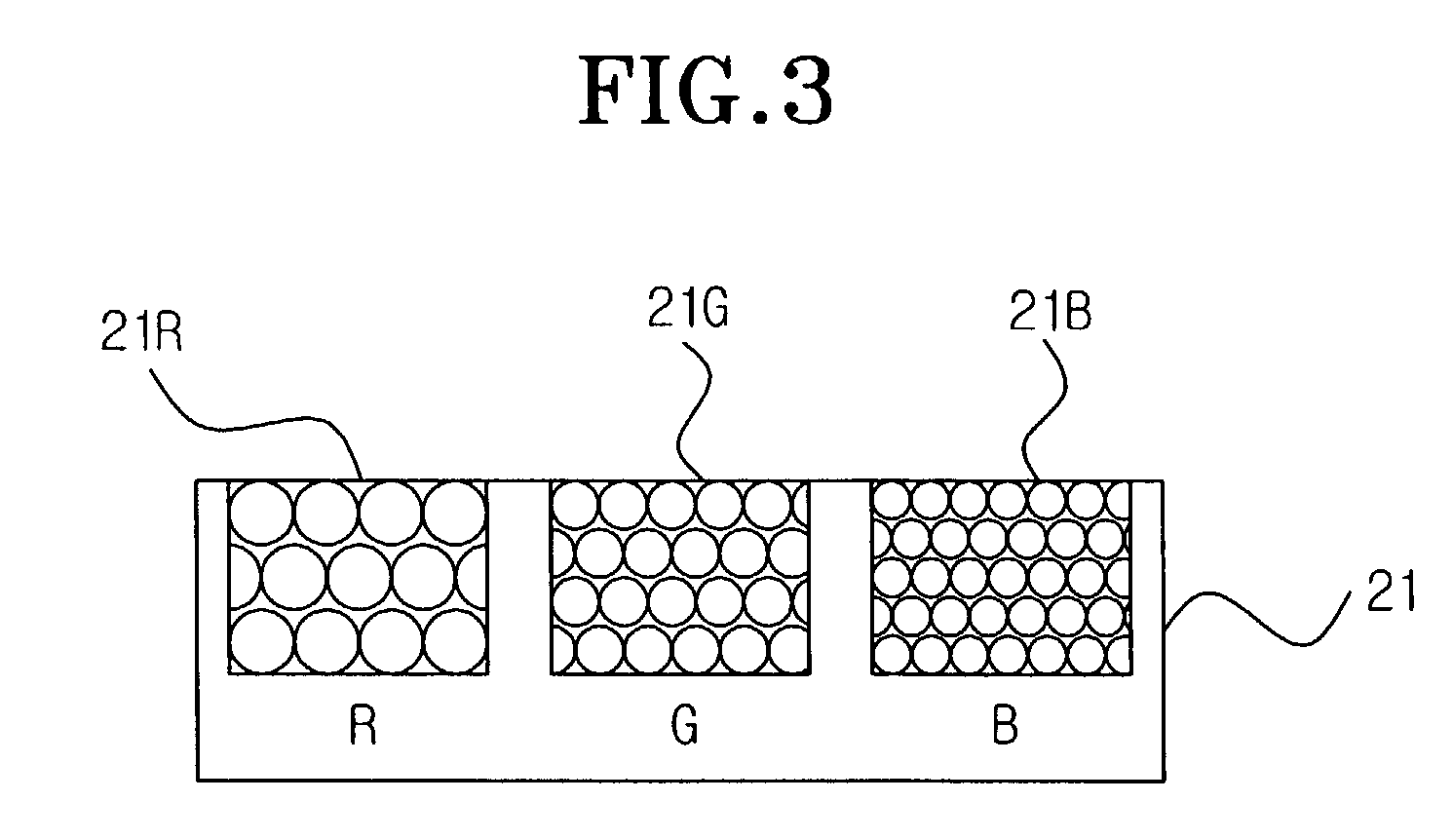
  • Reflective display device using photonic crystals
  • Reflective display device using photonic crystals
  • Reflective display device using photonic crystals

Examples


Embodiment Construction

[0019]Korean Patent Application No. 2002-23575, filed on Apr. 30, 2002, and entitled: “Reflective Display Device Using Photonic Crystals,” is incorporated by reference herein in its entirety.

[0020]The present invention will now be described more fully hereinafter with reference to the accompanying drawings, in which preferred embodiments of the invention are shown. The invention may, however, be embodied in different forms and should not be construed as limited to the embodiments set forth herein. Rather, these embodiments are provided so that this disclosure will be thorough and complete, and will fully convey the scope of the invention to those skilled in the art. In the drawings, the thickness of layers and regions are exaggerated for clarity. Like numbers refer to like elements throughout.

[0021]FIG. 2 illustrates a sectional view of a reflective display device according to an embodiment of the present invention.

[0022]As shown in FIG. 2, a reflective display device includes a ref...


PUM


Abstract

A reflective display device using photonic crystals includes a plurality of reflective color filters, each reflective color filter reflects a predetermined wavelength range of an incident visible light; and a plurality of optical switches disposed adjacent to and facing a corresponding one of the plurality of reflective color filters, each of the plurality of optical switches extracts a predetermined color by adjusting an intensity or on / off-frequency of light reflected from the corresponding one of the plurality of reflective color filters. Accordingly, a reflective display device using photonic crystals may have a simplified structure requiring no conventional reflecting mirror.

Description

BACKGROUND OF THE INVENTION[0001]1. Field of the Invention[0002]The present invention relates to a reflective display device. More particularly, the present invention relates to a reflective display device using photonic crystals that improves the optical efficiency due to the selective reflection and high reflectivity of photonic crystal structures.[0003]2. Description of the Related Art[0004]A display device of a portable device, such as a mobile phone or a personal digital assistant (PDA), uses a reflective color display to project an image using the reflection of the surrounding light. Accordingly, there is no need for backlight in such a reflective color display, thereby making the portable device lightweight, thin, and less power consumptive.[0005]In order to make a desired color, such reflective display devices use color filters. Therefore, the efficiency of the color filter is critical to obtaining a vivid display. A color filter produces a desired color by passing light of ...

Claims


Application Information

Patent Timeline
IPC IPC(8): G02F1/1335G02B5/18G02B6/122G09F9/30
CPCB82Y20/00G02B6/1225G02F1/133514G02F2202/32G02F1/133553G02F2001/133521G02F1/133521G02F1/1335
Inventor LEE, HONG-SEOKLEE, SUK-HANKIM, JI-DEOGMOON, IL-KWON
Owner SAMSUNG ELECTRONICS CO LTD
Learn More