

Lighting apparatus
- Summary
- Abstract
- Description
- Claims
- Application Information
AI Technical Summary
Benefits of technology
Problems solved by technology
Method used
Image

Examples
embodiment one
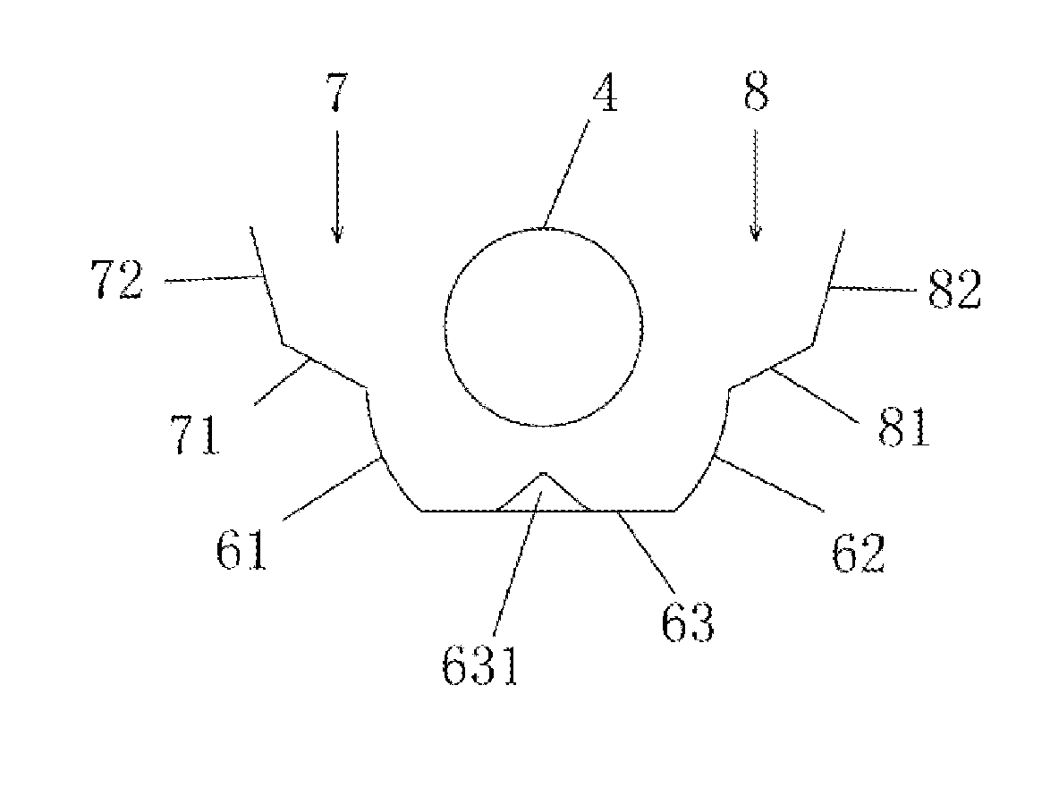
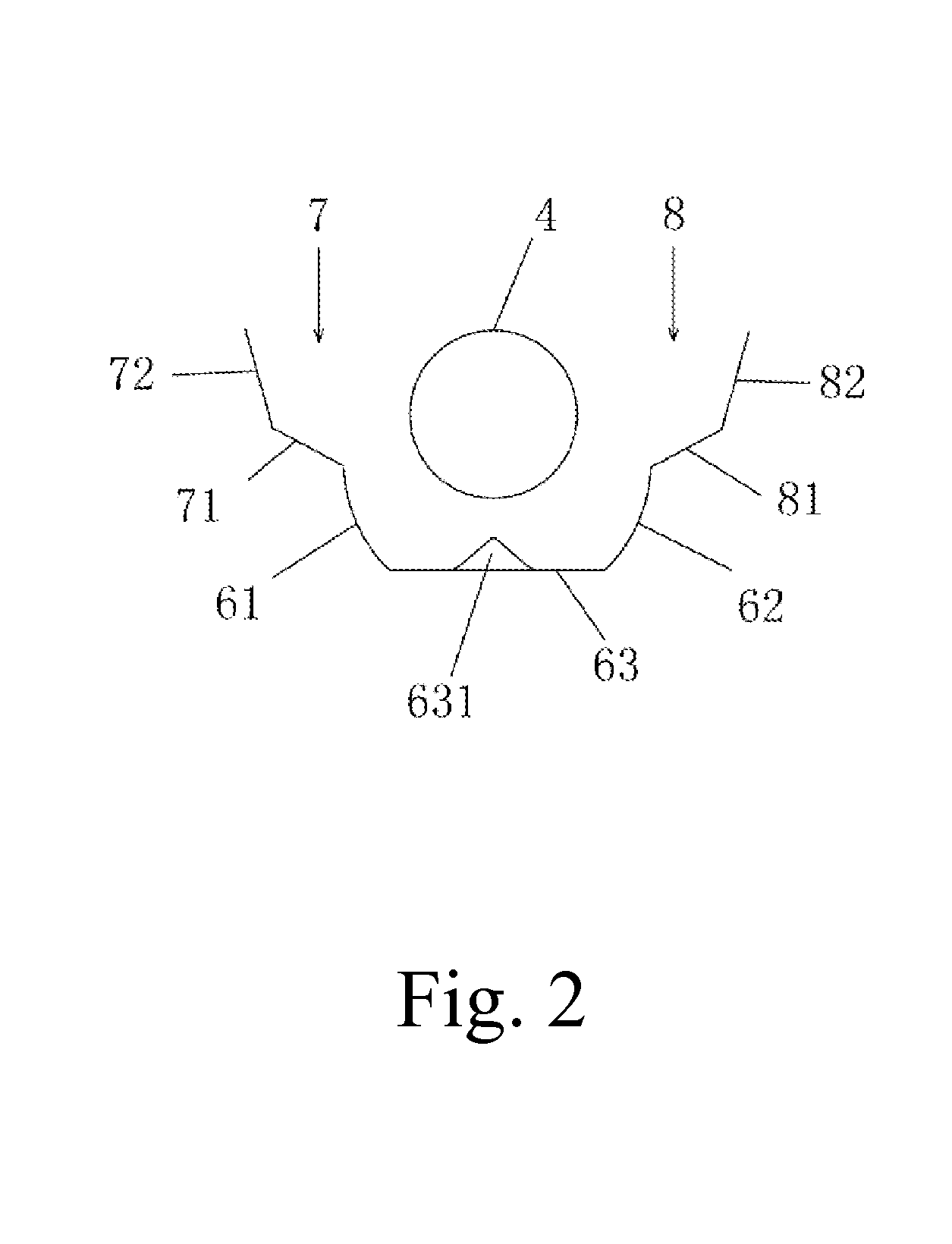
[0041]Referring to FIG. 3, according to a first preferred embodiment of the present invention, the reflector 19 includes a first reflecting element 7, a second reflecting element 8 opposite to the first reflecting element 7, and a reflector bottom 78 connected to lower ends of the first reflecting element 7 and the second reflecting element 8, so as to define a semi-closed internal space, for containing the bar-shaped lamp 4, wherein the first reflecting element 7 and the second reflecting 8 respectively have at least an outwardly-bent reflecting part for reflecting out light possibly much, so as to improve reflecting efficiency.
[0042]Preferably, the first reflecting element 7 has a first part 71 extending from the reflector bottom 78 and bending outwardly, for forming a first reflecting part and enlarging reflecting angles to reduce an amount of light reflected onto the bar-shaped lamp 4, and a second part 72 extending from the first part 71 and bending inwardly, for gathering and ...
embodiment two
[0055]Referring to FIGS. 4 and 5, according to a second preferred embodiment of the present invention, the first reflecting element 7, the second reflecting element 8 and the reflector bottom 78 of the reflector 19 form a concave slot, wherein reflecting material 5 is provided thereon; the first reflecting element 7 forms a first slot arm 1; the second reflecting element 8 forms a second slot arm 2; the reflector bottom 78 forms a slot bottom 3; and 4 denotes the bar-shaped lamp.
[0056]The slot bottom 3 is respectively connected to the first slot arm 1 and the second slot arm 2, wherein the first slot arm 1 and the second slot arm 2 are opposite to each other. The bar-shaped lamp 4 is provided above the slot bottom 3. The first slot arm 1, the slot bottom 3 and the second slot arm 2 are identical in shape and connected successively.
[0057]The reflecting material 5 is provided on the slot arm or the slot bottom of the concave slot and exposed under the bar-shaped lamp 4; a shape of the...
embodiment three
[0066]Referring to FIGS. 6-7, according to a third preferred embodiment of the present invention, the reflector 19 includes a concave slot and reflecting material, wherein the concave slot includes a first slot arm 9, a second slot arm 10 and a slot bottom 11, wherein the bar-shaped lamp 4 is provided above the slot bottom 11; and the reflecting material is a reflecting film covering a surface of the concave slot exposed under the bar-shaped lamp 4.
[0067]FIG. 6 shows a cross section of the first slot arm 9, including two arcs 91 which are serially connected and both bulge towards the bar-shaped lamp 4, wherein each arc 91 has an upper part 911 bending outwardly to define a reflecting part and enlarge reflecting angles, so as to reduce an amount of the light reflected onto the bar-shaped lamp 4, and a lower part 912 bending inwardly to gather and reflect dispersed light onto the surface of the opposite slot arm. The first slot arm 9 and the second slot arm 10 are symmetrical.
[0068]Fu...
PUM
| Property | Measurement | Unit |
|---|---|---|
| Shape | aaaaa | aaaaa |
| Efficiency | aaaaa | aaaaa |
| Reflection | aaaaa | aaaaa |
Abstract
Description
Claims
Application Information