
Method and apparatus for mapping pulses to a non-fixed layout

a technology of pulses and layouts, applied in the field of impulse radio systems, can solve the problems of limiting the performance of systems that use continuous sinusoidal waveforms, hardware limitation on the minimum pulse-to-pulse time, and the use of very little power of impulse radio transmitters to generate noise-like communication signals

Inactive Publication Date: 2006-12-05
TDC ACQUISITION HLDG
View PDF23 Cites 90 Cited by
  • Summary
  • Abstract
  • Description
  • Claims
  • Application Information

AI Technical Summary

Benefits of technology

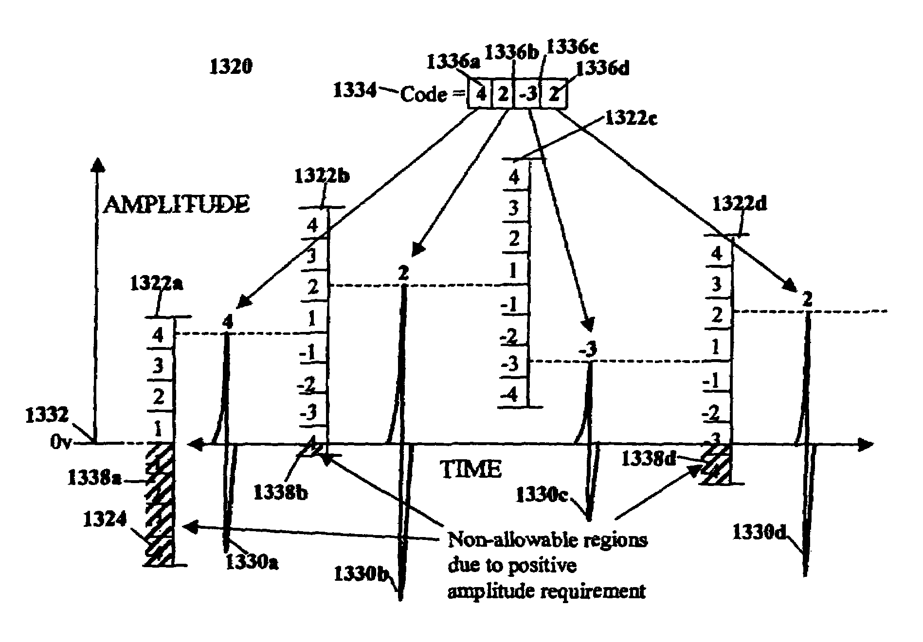
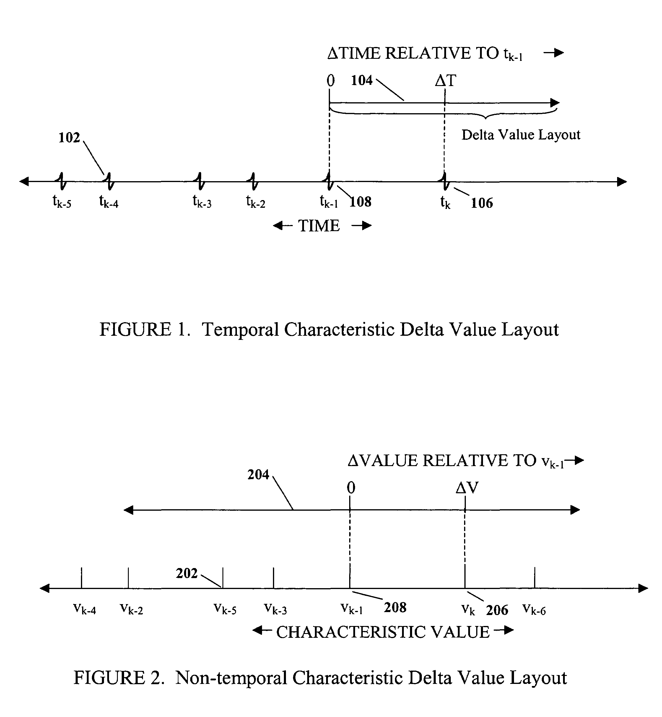
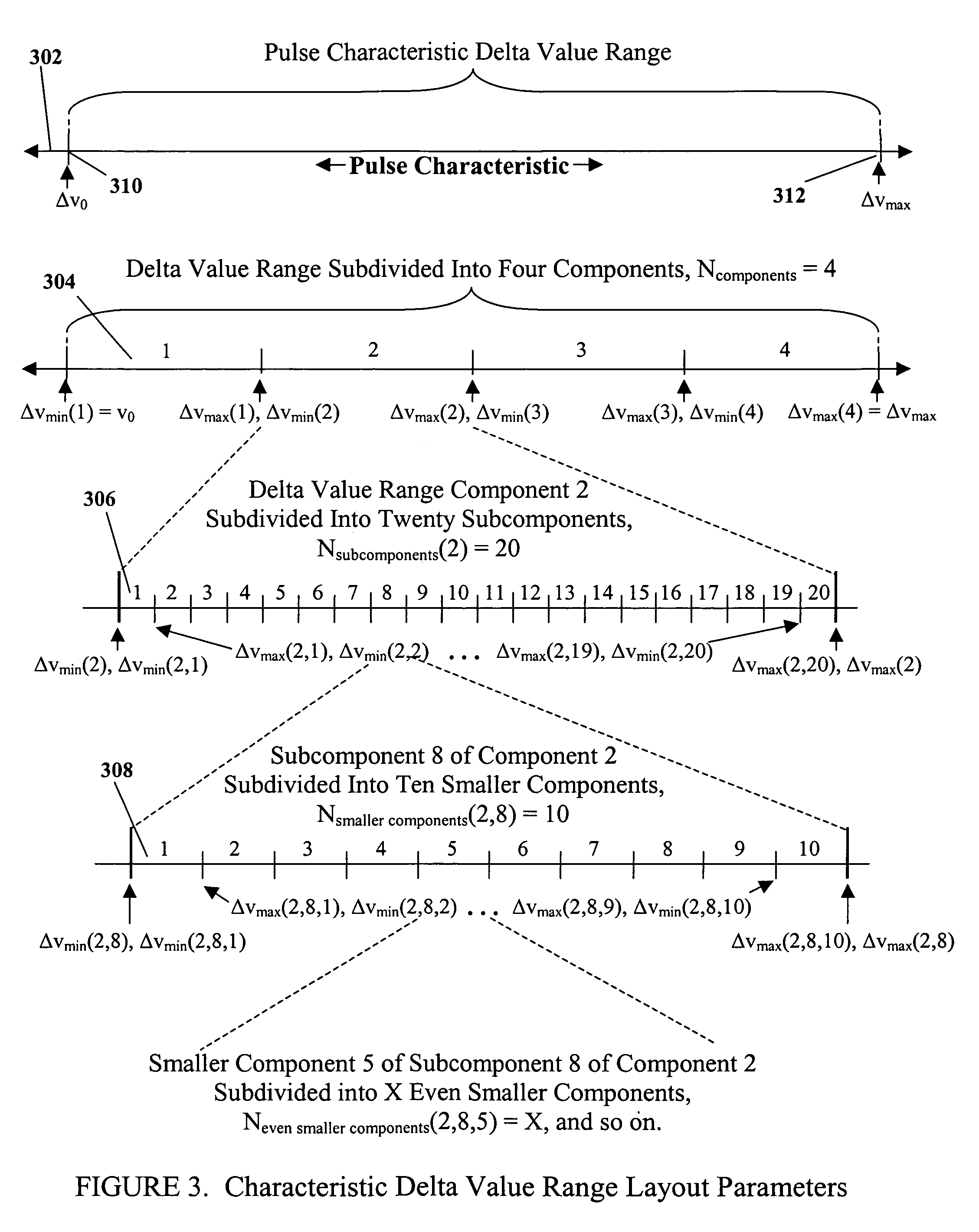
[0029]Briefly, according to the present invention, a coding method specifies temporal and/or non-temporal pulse characteristics in accordance with at least one non-fixed layout of characteristic delta value ranges and/or discrete delta values. Temporal pulse characteristics, for example, include time position. Non-temporal pulse characteristics, for example, include pulse amplitude and pulse width and other kno

Problems solved by technology

As a result, the impulse radio transmitter uses very little power to generate noise-like communication signals for use in multiple-access communications, radar and positioning applications, among other things.
Because of the extremely high achievable processing gains, the impulse radio systems are relatively immune to unwanted signals and interference, which limit the performance of systems that use continuous sinusoidal waveforms.
Because of practical limitations associated with arbitrarily positioning of pulses in adjacent frames, each frame may have to be divided into allowable and non-allowable time regions for positioning a pulse.
One such limitation is associated with hardware limitation on minimum pulse-to-pulse time for respective positioning of two pulses on adjacent frames arbitrarily.
Such predictability opens the possibility of undesired signal interception by third parties, and is thus a liability for certain UWB applications, such as secure communications.
In addition, the specific code-generation methodology presented in McCorkle imposes limitations on the resulting codes that may not be acceptable for some applications.
Finally, the coding techniques in both Barrett and McCorkle are limited to determining the temporal positioning of pulses emitted by UWB transmitters.

Method used


Image

  • Method and apparatus for mapping pulses to a non-fixed layout
  • Method and apparatus for mapping pulses to a non-fixed layout
  • Method and apparatus for mapping pulses to a non-fixed layout

Examples


Embodiment Construction

[0090]A preferred embodiment of the invention is discussed in detail below. While specific implementations are discussed, it should be understood that this is done for illustration purposes only. A person skilled in the relevant art will recognize that other components and configurations may be used without parting from the spirit and scope of the invention.

I. Overview

[0091]In a time-hopping pulse transmission system, a sequence of pulses known as a pulse train is transmitted and received over a period of time. The relative positioning of the pulses in time defines a channel used by the system to transmit information. Time-hopping pulse transmission systems transmit these pulses such that they have the same non-temporal (i.e., non-time dependent) characteristics while varying the precise timing of the pulses per a time-hopping code mapped to frame-based time layout. (Non-temporal characteristics include amplitude, width, and other non-time dependent characteristics of a pulse or ser...


PUM


Abstract

A coding method, specifies temporal and / or non-temporal pulse characteristics, where pulse characteristic values are relative to one or more non-fixed reference characteristic values within at least one delta value range or discrete delta value layout. The method allocates allowable and non-allowable regions relative to the one ore more non-fixed references. The method applies a delta code relative to the allowable and non-allowable regions. The allowable and non-allowable regions are relative to one or more definable characteristic values within a characteristic value layout. The one or more definable characteristic values are relative to one or more characteristic value references. In addition, the one or more characteristic value references can be a characteristic value of a given pulse such as a preceding pulse or a succeeding pulse.

Description

CROSS-REFERENCE TO OTHER APPLICATIONS[0001]This application is a Continuation-in-Part of Ser. No. 09 / 591,691, filed Jun. 12, 2000.[0002]The following applications of common assignee may contain common disclosure with the present application:[0003]U.S. patent application Ser. No. 09 / 592,250 entitled “A METHOD FOR SPECIFYING NON-TEMPORAL PULSE CHARACTERISTICS”, filed concurrently herewith.[0004]U.S. patent application Ser. No. 09 / 591,690 entitled “A METHOD AND APPARATUS FOR APPLYING CODES HAVING PRE-DEFINED PROPERTIES”, filed concurrently herewith.[0005]U.S. patent application Ser. No. 09 / 592,249 entitled “A METHOD AND APPARATUS FOR POSITIONING PULSES USING A LAYOUT HAVING NON-ALLOWABLE REGIONS”, filed concurrently herewith.[0006]U.S. patent application Ser. No. 09 / 592,248 entitled “A METHOD AND APPARATUS FOR POSITIONING PULSES IN TIME”, filed concurrently herewith.[0007]U.S. patent application Ser. No. 09 / 592,288 entitled “A METHOD AND APPARATUS FOR SPECIFYING PULSE CHARACTERISTICS U...

Claims


Application Information

Patent Timeline
IPC IPC(8): H04B14/06
CPCH04B1/7172H04B1/7176H04B1/719
Inventor PENDERGRASS, MARCUS H.ROBERTS, MARK D.RICHARDS, JAMES L.
Owner TDC ACQUISITION HLDG
Learn More