Device for muscle stimulation

a neuroprosthetic device and muscle technology, applied in the field of surface neuroprosthetic devices for muscle stimulation, can solve the problems of geometric distortion of the soft tissue of the limb, the wide use of surface neuroprostheses, and the high level of expertise required to position the electrode array, and achieve the effect of convenient donned and doffed

Inactive Publication Date: 2006-12-05
BIONESS NEUROMODULATION
View PDF7 Cites 59 Cited by
  • Summary
  • Abstract
  • Description
  • Claims
  • Application Information

AI Technical Summary

Benefits of technology

[0005]It is therefore one of the objects of the present invention to provide a neuroprosthetic device tha

Problems solved by technology

One of the main barriers to widespread use of surface neuroprostheses has been the lengthy time and high level of expertise required to position the electrode array and to hold the elec

Method used


Image

  • Device for muscle stimulation
  • Device for muscle stimulation
  • Device for muscle stimulation

Examples


first embodiment

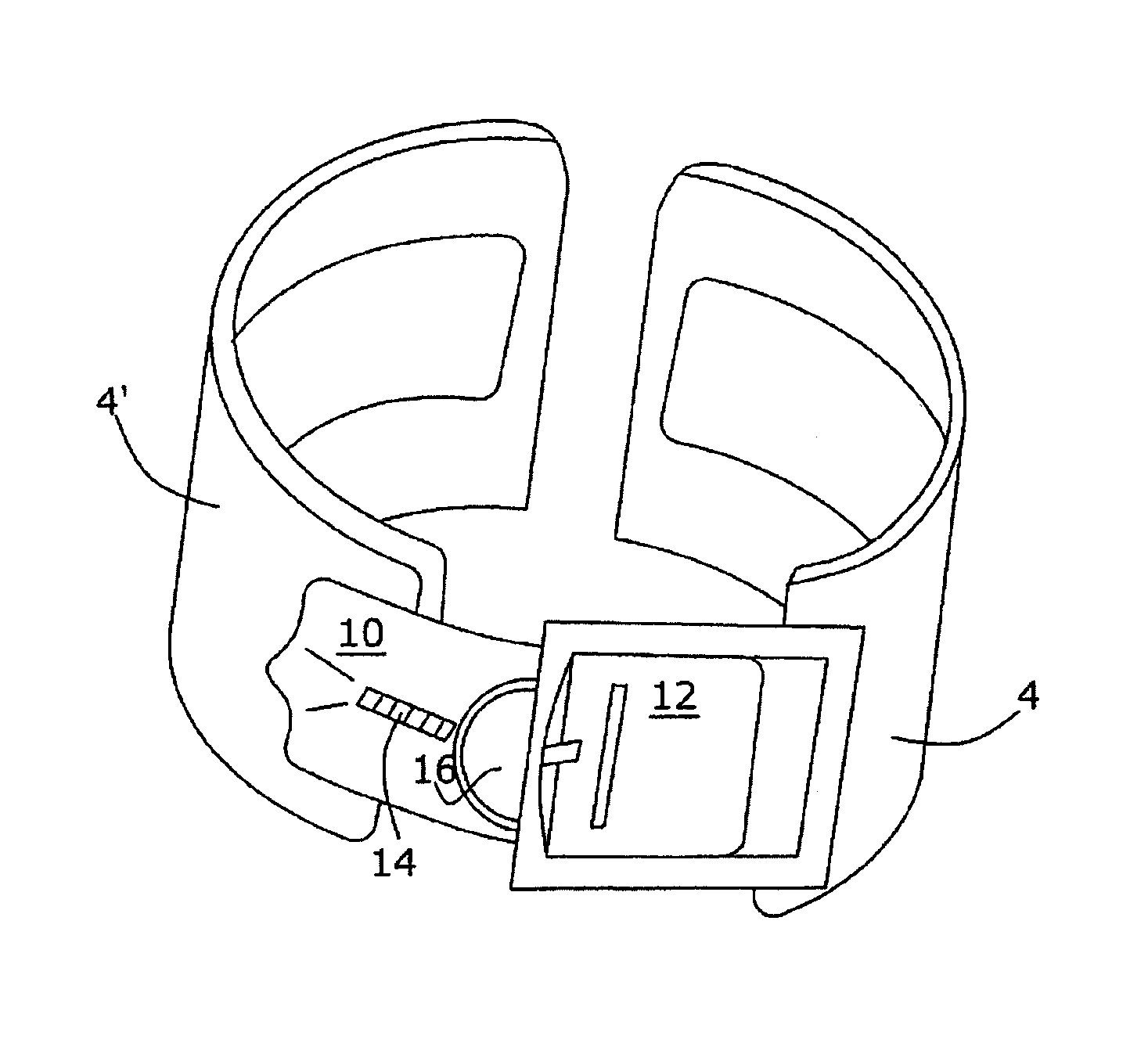
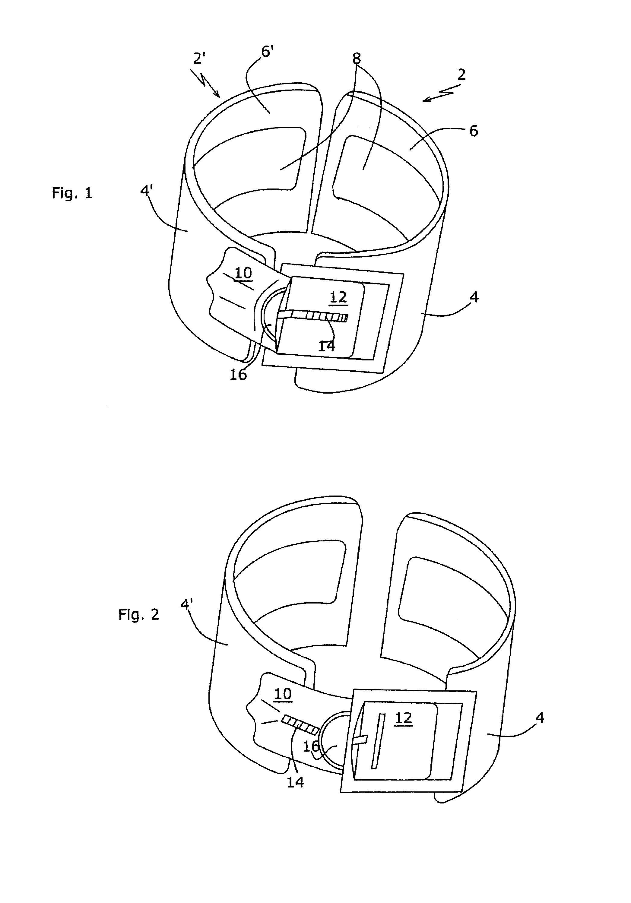
[0074]Referring now to the drawings, there is shown in FIG. 1 the device according to the present invention. The device is shown in one of its limit states, in which the split-sleeve-like structure is fully closed. The device, as illustrated, is intended to be worn on the upper arm, as shown in FIG. 6c. Seen are an anterior shell 2 and a posterior shell 2′, consisting of at least semi-rigid outer members 4, 4′ and elastically yielding, back-up or cushion members 6, 6′. The two shells 2, 2′ and their cushions 6, 6′ substantially envelop the entire circumference of the upper arm segment at the approximate center of the length of the arm, at the midpoint of the biceps muscle. The interior of shells 2, 2′, when mounted on the arm, has a substantially barrel-like shape, which reflects the geometry of the upper arm. Also shown are electrodes 8, each shell 2, 2′ being provided with two electrodes, by way of example.

[0075]A characterizing feature of the device of the present invention is th...

second embodiment

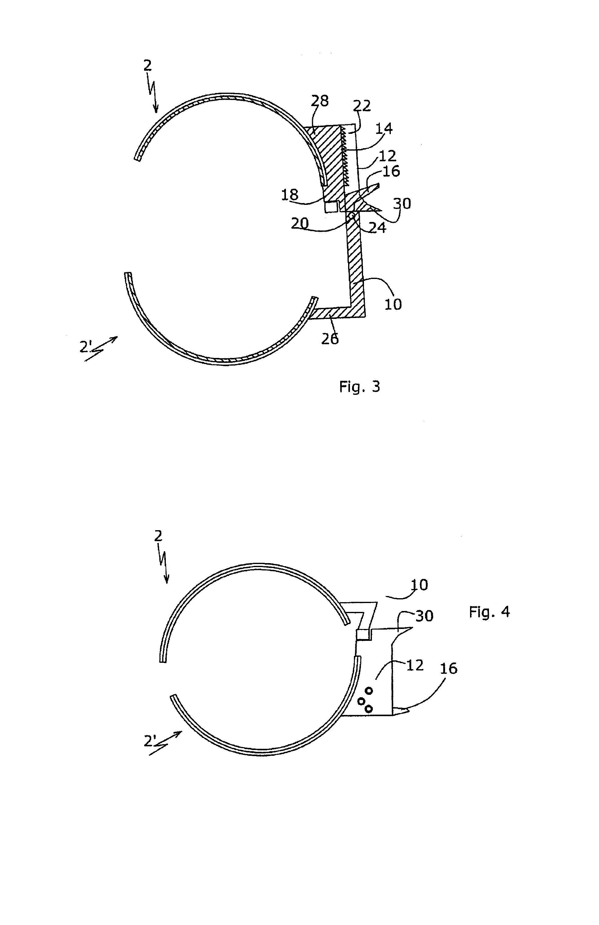
[0083]A full view of the mechanism is afforded by FIG. 3, which illustrates a cross-sectional view of the device in which ratchet 14 is an integral part of guide member 12 and is shown at the end of the linear movement thereof. Shown are slider 10, guide member 12, ratchet 14, release trigger 16 and pawl 18. The trigger 16 / pawl 18 unit is hingedly articulated to slider 10 by means of a pivot 20, and is spring-biased towards the position in which pawl 18 engages the saw teeth of ratchet 14.

[0084]To open the device for donning from its extreme limit of closure illustrated in FIG. 4, the thumb and index finger of the user are applied against pawl trigger 16 and counterhold 30, respectively, so as to disengage pawl 18 from ratchet 14 and push slider 10 out of guide member 12. At the end of the linear stroke, slide member 10 leaves guiding groove 22 (FIG. 3), at which instant, torsion spring 24 causes the now-free slider 10 to swivel up to about 20°, resulting in the shells 2, 2′ assumi...


PUM


Abstract

A device for muscle stimulation, including: two exoskeletal shells, each including an outer member including an at least semi-rigid material, the shells being configured to at least partly, surround a limb portion of a user, and kinematic connection means connecting the shells and providing the shells with at least one degree of freedom in translation, so as to enable the shells to move in a substantially linear movement with respect to each other.

Description

FIELD AND BACKGROUND OF THE INVENTION[0001]The present invention relates to a surface neuroprosthetic device for muscle stimulation.[0002]Movement impairment in a limb can result from a number of neurological or orthopedic pathological conditions. Activation of selected muscles of the limb by functional electrical stimulation (FES) to generate controlled movements has been used, both as a therapeutic modality and for the improvement or restoration of activities of daily living (ADL) or functional restoration.[0003]Devices based on surface electrical stimulation which have been developed for activating specific body sites include the dropfoot system, which activates the ankle joint, modifying hemiplegic gait; hybrid FES-orthosis systems for restoring gait in spinal cord-injured patients, and systems for therapeutic activation and functional restoration of the hand, such as the Handmaster, described in U.S. Pat. No. 5,330,516 (Nathan). Other prior art devices are described in U.S. Pat...

Claims


Application Information

Patent Timeline
IPC IPC(8): A61N1/18A61HA61N1/36A61H1/00A61H39/00A61N1/04A61N1/05
CPCA61N1/0452A61N1/0476A61N1/36003A61N1/36014A61N1/0472A61N1/0484
Inventor DAR, AMITNATHAN, ROGER
Owner BIONESS NEUROMODULATION
Why Eureka
Try Eureka