Service trolley for open-end spinning machines

a technology trolleys, which is applied in the direction of open-end spinning machines, piercing arrangements, continuous wounding machines, etc., can solve the problem that failure of one of the steps of the cycle has the consequence of failure of the entire cycl

Inactive Publication Date: 2006-12-12
SAVIO MACCHINE TESSILI
View PDF9 Cites 17 Cited by
  • Summary
  • Abstract
  • Description
  • Claims
  • Application Information

AI Technical Summary

Benefits of technology

[0028]The present invention is relative to a service trolley for open-end spinning machines, in which the individual operating steps in the cycles of the trolley are controlled one by one so that, in the case of failure of one of the steps, the trolley does not waste time pointlessly continuing with the sequence, but can restart the cycle from the unsuccessful step to repeat it, possibly with different operating parameters.
[0029]The purpose of the present invention is that of making a service trolley for open-end spinning machines that overcomes the described drawbacks of trolleys available in the state of the art and allows greater efficiency of the interventions and greater yield of the spinning machine to be obtained, reducing the idle time due to the repetition of interventions on spinning units.

Problems solved by technology

It is clear that the failure of one of the steps of the cycle has the consequence of the failure of the entire cycle.

Method used


Image

  • Service trolley for open-end spinning machines
  • Service trolley for open-end spinning machines
  • Service trolley for open-end spinning machines

Examples


Embodiment Construction

[0037]According to a preferred embodiment of the present invention the motors for the moving of the service members of the trolley are stepper motors driven in steps, again to obtain angular positions, speeds and accelerations that are controlled in each step of their operations in the two directions of rotation.

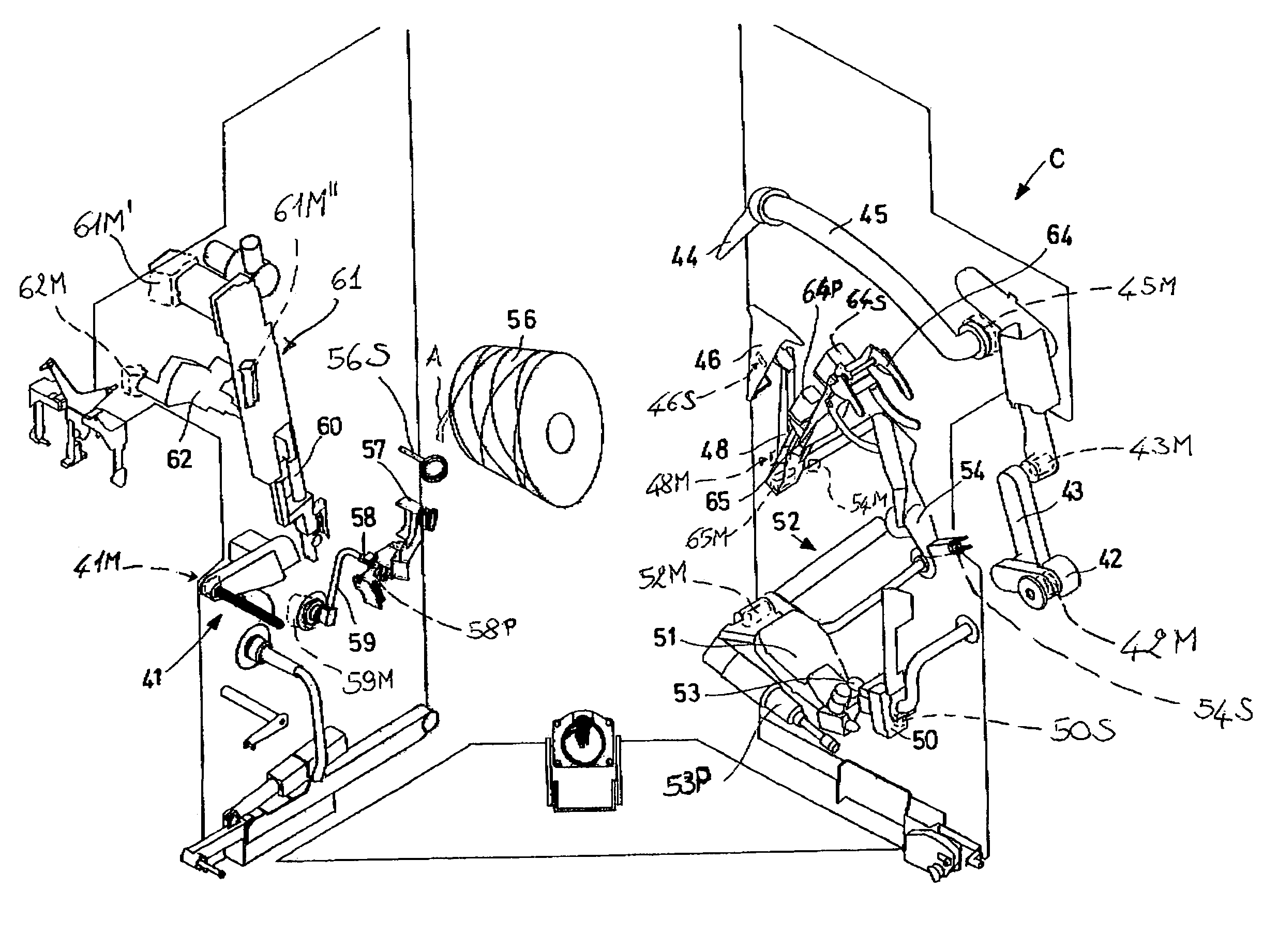
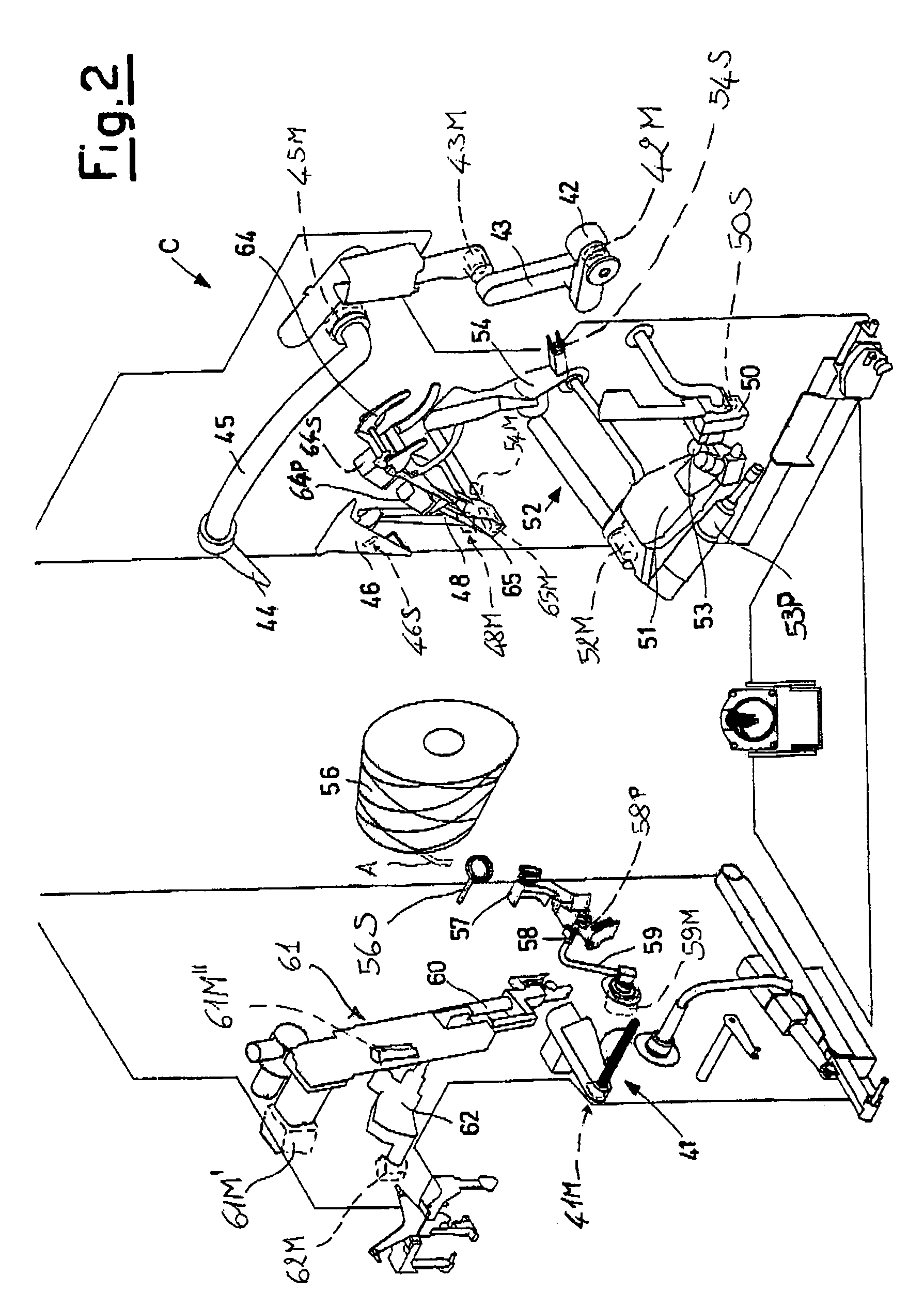
[0038]In the trolley C illustrated in the scheme of FIG. 2 its most significant members or groups for servicing the open-end spinning unit, for both the reattachment and lifting operation, are shown:[0039]a device 41 for controlling and positioning the thread F during the intervention cycles that acts, during the intervention cycles, to lift and determine the level and the position of the thread connected with the cone or with its quill with respect to other members of the trolley. The device 41 is moved in rotation with a motor 41M. The position taken up by the device 41 is controlled by an absolute encoder, i.e. a member for detecting the angular position of the motor;[004...


PUM

PropertyMeasurementUnit
speedaaaaaaaaaa
frequencyaaaaaaaaaa
speedsaaaaaaaaaa

Abstract

Service trolley for open-end spinning machines equipped with members dedicated to the operations in the intervention cycles and managed by the trolley's own control unit in which each member is independent from the others, being equipped with independent actuation controlled by sensors for the various steps of the intervention cycles.

Description

CROSS-REFERENCE TO RELATED APPLICATIONS[0001]Not ApplicableSTATEMENT REGARDING FEDERALLY SPONSORED RESEARCH OR DEVELOPMENT[0002]Not ApplicableINCORPORATION-BY-REFERENCE OF MATERIAL SUBMITTED ON A COMPACT DISK[0003]Not ApplicableREFERENCE TO A MICROFICHE APPENDIX[0004]Not ApplicableBACKGROUND OF THE INVENTION[0005](1) Field of the Invention[0006]The present invention refers to open end spinning, or rotor spinning. Open-end spinning machines generally consist of a plurality of individual spinning units, aligned on the two sides of the machine, each of which is made up of a spinning rotor, which produces twisted tread from singularised fibres of a rove, and a collection unit that—with the prior quality control of yarn with the interposition of a yarn clearer between the two components—carries the yarn to wind onto a quill to form a cone. This cone is thus formed pulling and winding the yarn on its surface, being pulled into rotation by the roller below on which the cone in formation is...

Claims


Application Information

Patent Timeline
Patent Type & Authority Patents(United States)
IPC IPC(8): B65H69/06D01H4/08D01H4/48D01H4/50D01H9/00D01H13/00
CPCD01H4/50D01H13/005
Inventor BADIALI, ROBERTOCOLUSSI, VITTORIOCASTELLARIN, DONATO
Owner SAVIO MACCHINE TESSILI
Why Eureka
Try Eureka