Machine to recover a cable

a cable recovery machine and cable technology, applied in the direction of overhead line/cable accessories, fluid gearings, gearing elements, etc., can solve the problems of not being able to bring the hydraulic pump, the device that limits and controls the overload cannot guarantee the complete safety of stringing operations, etc., to achieve high safety and effective intervention

Pending Publication Date: 2022-06-30
TESMEC
View PDF0 Cites 0 Cited by
  • Summary
  • Abstract
  • Description
  • Claims
  • Application Information

AI Technical Summary

Benefits of technology

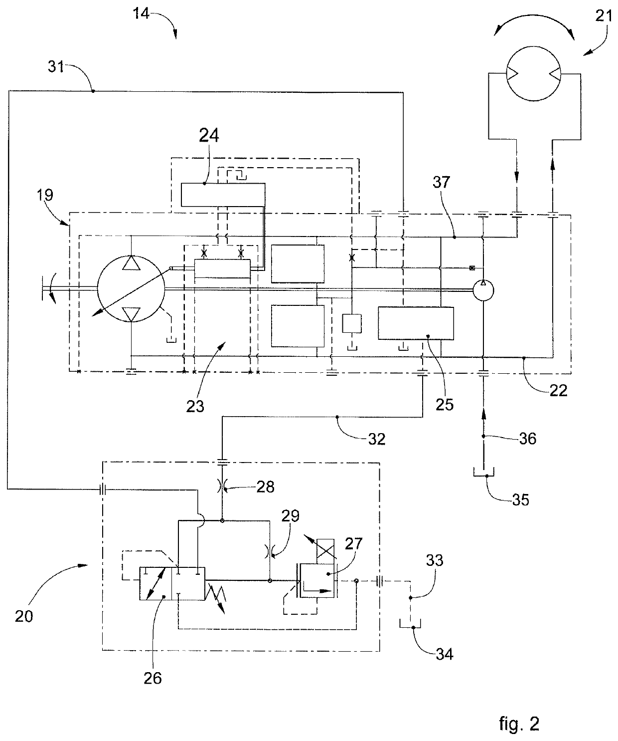
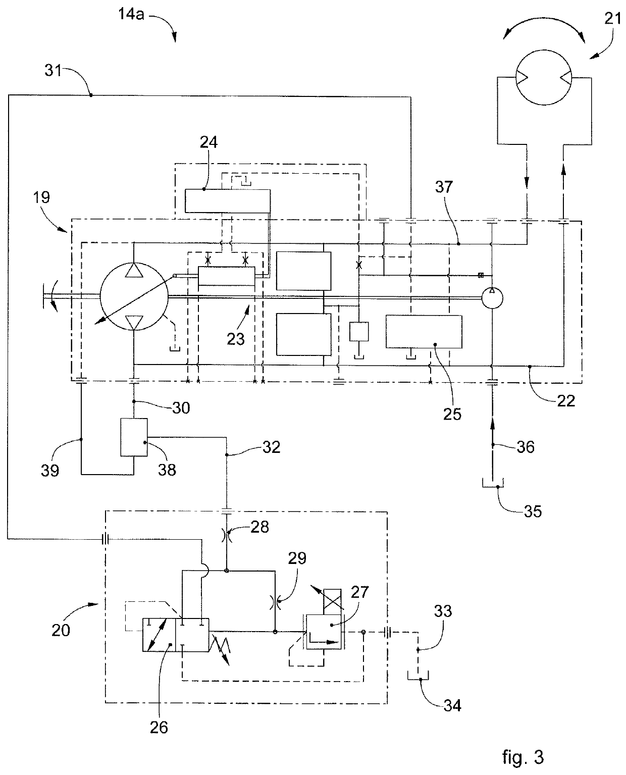
[0019]Advantageously, thanks to the possibility of placing the pilot channel of the servo controller integrated in the hydraulic pump in discharge conditions, when the set pressure limit is reached, the fluid necessary for the shutter of the hydraulic pump substantially fails, and it then returns to the zero position, that is, to the inactive position, maintaining the pressure in the circuit and therefore the set drawing value, that is, the tension value set for the cable to be drawn. In this way, the cable cannot be unwound by the recovery machine, thus guaranteeing high safety and effective intervention in the event of overload situations on the cable. The adjustment device with which the recovery machine is equipped therefore functions as a safety system for the proportional limitation of the drawing action applied to the cable, thanks in particular to the use of the piloted proportional valve.

Problems solved by technology

In fact, the possibility that the cable can be unwound even in overload situations does not guarantee complete safety in the stringing operations.
Substantially, therefore, the known device that limits and controls the overload is not able to bring the hydraulic pump to a cubic capacity such as to stop the movement of the hydraulic motor while maintaining the set pressure, which would allow to maintain the drawing action on the line and therefore not release the cable or conductor.

Method used


Image

  • Machine to recover a cable
  • Machine to recover a cable
  • Machine to recover a cable

Examples


Embodiment Construction

[0036]We will now refer in detail to the various embodiments of the present invention, of which one or more examples are shown in the attached drawings. Each example is supplied by way of illustration of the invention and shall not be understood as a limitation thereof. For example, the characteristics shown or described insomuch as they are part of one embodiment can be adopted on, or in association with, other embodiments to produce another embodiment. It is understood that the present invention shall include all such modifications and variants.

[0037]Before describing these embodiments, we must also clarify that the present description is not limited in its application to details of the construction and disposition of the components as described in the following description using the attached drawings. The present description can provide other embodiments and can be obtained or executed in various other ways. We must also clarify that the phraseology and terminology used here is f...


PUM


Abstract

Machine to recover a cable, comprising at least one hydraulic pump with variable cubic capacity, provided with a system to adjust the cubic capacity, driven by a servo controller, and at least one hydraulic motor fed by said hydraulic pump by means of at least one pipe to deliver a fluid and at least one pipe to return the fluid.

Description

FIELD OF THE INVENTION[0001]The present invention concerns a cable recovery machine, usable, in particular, in a plant, for example, for stringing a high voltage overhead power line and in general in overhead lines which provide the so-called “braked” stringing of cables, or overhead conductors.[0002]In particular, the present invention concerns a cable recovery machine equipped with an adjustment device able to guarantee maximum safety in cable recovery operations.BACKGROUND OF THE INVENTION[0003]It is known that the traditional system for stringing an electric line provides the so-called “braked” stringing by means of machines with multiple capstans: a winch machine, which recovers a cable, such as for example a steel cable with a drawing function, and a brake machine, which applies a controlled tension to the conductors in the stringing step so as to ensure that they can remain suspended to the appropriate guide devices provided on the intermediate supports, so that they do not s...

Claims


Application Information

Patent Timeline
Patent Type & Authority Applications(United States)
IPC IPC(8): F16H61/4017F16H61/431F16H39/02H02G1/04
CPCF16H61/4017H02G1/04F16H39/02F16H61/431
Inventor OSCAR, ALBERTOPARODI, FABRIZIOPEDROCCHI, ROBERTO
Owner TESMEC
Why Eureka
Try Eureka