Front part structure of vehicle body

a technology for front parts and vehicles, applied in vehicle maintenance, roofs, vehicle cleaning, etc., can solve problems such as the inability to provide gussets between them

Active Publication Date: 2006-12-12
HONDA MOTOR CO LTD
View PDF5 Cites 46 Cited by
  • Summary
  • Abstract
  • Description
  • Claims
  • Application Information

AI Technical Summary

Benefits of technology

[0007]An object of the present invention is to provide a front part structure of a vehicle body arranged: (1) such that a dashboard for partitioning a front part of the vehicle body into an engine compartment defined forwardly of the dashboard and a passenger compartment defined rearwardly of the dashboard is disposed in a forwardly shifted position so as to enlarge the passenger compartment; (2) such that a collision energy applied to front side frames from a front side of the vehicle body is efficiently distributed to front pillars; and (3) such that front damper housings are reinforced.
[0009]The reinforcing member extends between the front upper member and the joining portion where the front damper housing is joined to the front side frame. The reinforcing member is joined to the rear part of the damper housing therealong. This arrangement of the reinforcing member enables sufficient reinforcement of the front damper housing.
[0013]The front part structure of the vehicle body has the following advantages: (1) a collision energy applied to the front side frame from a front side of the vehicle body can be distributed to the front pillar through the reinforcing member and the front upper member; (2) the front damper housing can be reinforced by the reinforcing member; and (3) the dashboard partitioning the front part of the vehicle body into the engine compartment defined forwardly of the dashboard and the passenger compartment defined rearwardly of the dashboard is adjacent to the rear part of the front damper housing so as to enlarge the passenger compartment.
[0014]The closed cross-sectional member is the form of a substantially straight line, as viewed in all of front elevation, top plan and side elevation. By virtue of the substantially linearly extending closed cross-sectional member, the collision energy applied to the front side frame from the front side of the vehicle body can be efficiently distributed to the front pillar.
[0018]With this arrangement, the reinforcing upper half portion is smaller in strength than the reinforcing lower half portion and the second reinforcing part. The reinforcing member has strength suitable for achieving an optimal proportion of collision energy to be distributed from the front side frame to the front pillar to the collision energy applied to the front side frame from the front side of the vehicle body. Thus, the vehicle body can be more freely designed.

Problems solved by technology

Where only a small or no space is formed between the damper housings and the dashboard, the gussets can not be provided therebetween.

Method used


Image

  • Front part structure of vehicle body
  • Front part structure of vehicle body
  • Front part structure of vehicle body

Examples


Embodiment Construction

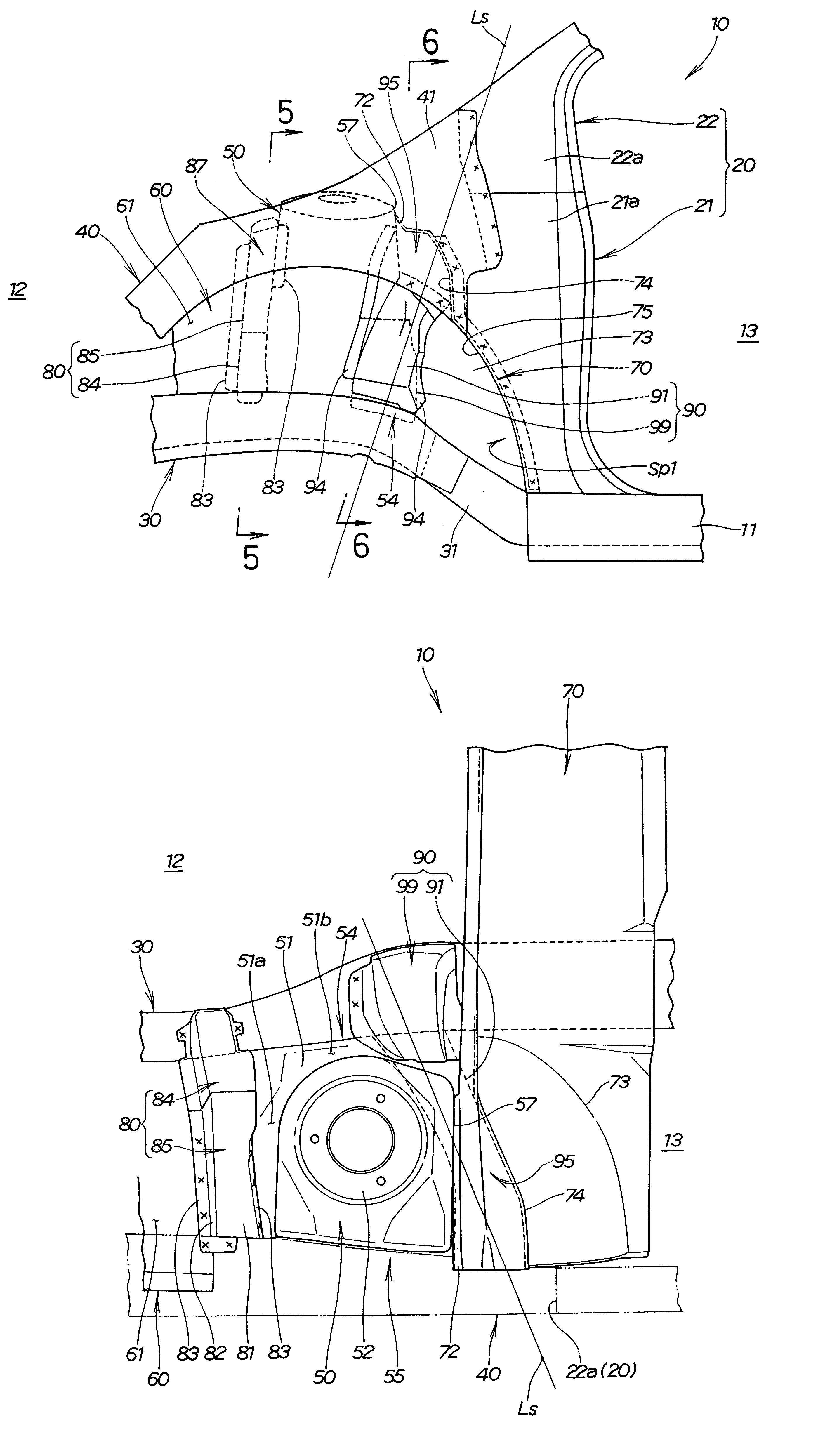
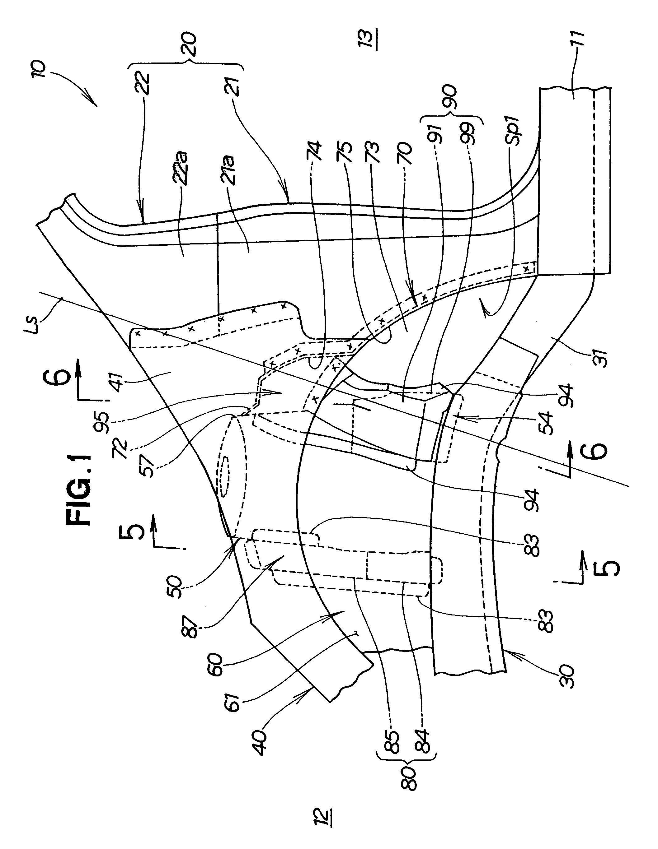
[0028]In the drawings, only a left half of a front part of a vehicle body is shown. A right half of the front part of the vehicle body has the same arrangement as the left half, and a detailed description as to the right half of the front part of the vehicle body will be omitted. Welding such as spot welding is used for joining together components as explained hereinbelow.

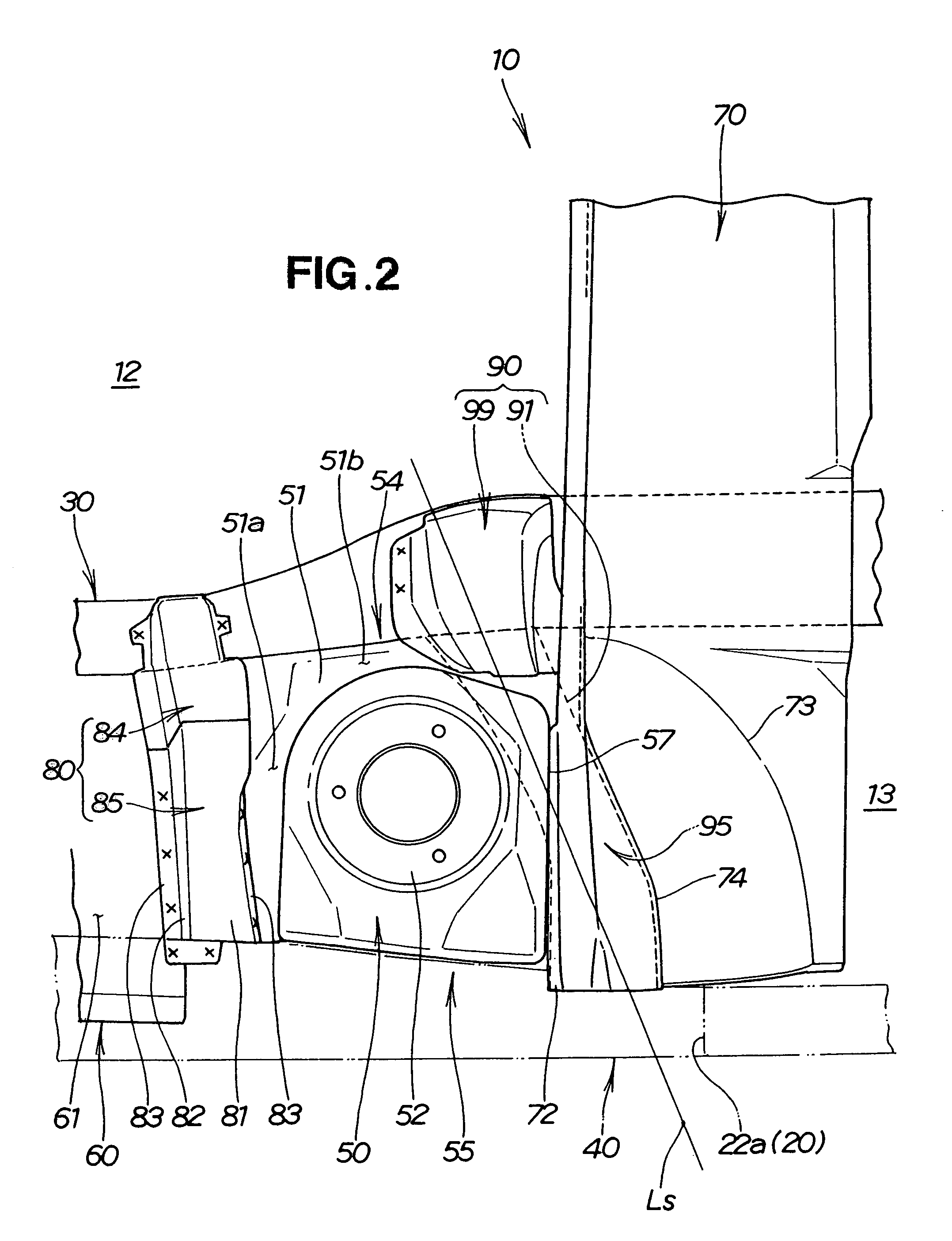
[0029]Referring to FIG. 1 and FIG. 2, a vehicle body (i.e., a vehicle body frame) 10 of a vehicle such as an automobile is a monocoque body including right and left side sills 11, right and left front pillars 20, right and left front side frames 30, right and left front upper members 40, right and left front damper housings 50, right and left wheel houses 60 and a dashboard 70.

[0030]The right and left side sills 11 extend in a front-and-rear direction of the vehicle body 10 and are disposed on right and left sides of the vehicle body 10, respectively. The right and left front pillars 20 extend upwardly from front e...


PUM


Abstract

A vehicle body includes a front part having a dashboard. The dashboard has an upper end portion bulged in a rearward direction of the vehicle body. The bulged upper end portion covers an upper portion of a rear reinforcing member with a constant interval provided therebetween. The bulged upper end portion is joined to an upper member and a damper housing. The bulged upper end portion and the rear reinforcing member are combined together to form a closed cross-sectional member directed towards a front pillar and extending from a side frame to the upper member. The rear reinforcing member extends from a lower joining portion located forwardly of a lower part of the dashboard through inside of the bulged upper end portion to the upper member. The rear reinforcing member takes the form of a generally straight line, as viewed in all of front elevation, top plan and side elevation.

Description

FIELD OF THE INVENTION[0001]The present invention relates to an improvement in a front part structure of a vehicle body for dispersing a collision energy applied to the front part from a front side of the vehicle body.BACKGROUND OF THE INVENTION[0002]Vehicle bodies of vehicles such as automobiles include right and left front side frames disposed on right and left sides of front parts of the vehicle bodies and extending in a front-and-rear direction of the vehicle bodies. In recent years, structures of the front parts of the vehicle bodies have been developed to distribute to front pillars collision energies applied to the front side frames from front sides of the vehicle bodies, as disclosed in JP-A-2003-182633, so as to reduce burdens to be borne by rear end portions of the front side frames.[0003]FIG. 8A and FIG. 8B hereof show a right half of a front part of a conventional vehicle body 100 shown in JP-A-2003-182633. The vehicle body 100 includes right and left front side frames 1...

Claims


Application Information

Patent Timeline
Patent Type & Authority Patents(United States)
IPC IPC(8): B62D25/08
CPCB62D25/082B62D25/088
Inventor MATSUYAMA, SHOHEIBOETTCHER, ERIC J.
Owner HONDA MOTOR CO LTD
Why Eureka
Try Eureka