
Device for treating flat material

a flat material and flat technology, applied in the field of flat material treatment devices, can solve the problems of unsuitable materials devices are unsuitable for precise fine embossing and satinizing, and the arrangement is unsuitable for satinizing or for embossing special signs, etc., to achieve the effect of high precision and difficult copying

Inactive Publication Date: 2006-12-12
BOEGLL GRAVURES SA
View PDF40 Cites 93 Cited by
  • Summary
  • Abstract
  • Description
  • Claims
  • Application Information

AI Technical Summary

Benefits of technology

The present invention provides a device for producing embossed patterns that allows signs with optical effects that depend on the viewing position and / or the light source to be embossed on flat materials with higher precision and in a wider variety in order to produce security features that are difficult to copy. The device allows for the embossing of a large range of flat materials with signs providing optical effects that depend on the viewing position and / or the light source with higher precision and in a wider variety.

Problems solved by technology

However, such an arrangement is unsuitable for satinizing or for embossing special signs on materials such as cigarette paper as the embossing rolls, which are not described in detail and are illustrated with a relatively coarse profile, are not intended for this purpose.
Such pairs of rolls with recesses in a rubber roll are unsuitable for a precise fine embossing and satinizing as it is required e.g. for the treatment of packaging foils where the flat material is a fibrous material such as paper which is bulked after the treatment.
This device is also unsuitable for a precise fine embossing and satinizing.
A device of this kind is neither appropriate for embossing nor for satinizing, and it is also inappropriate for embossing security features on suitable materials.
Whereas the first mentioned device according to WO-A-00 / 69622 provided the expected advantages in the embossing of flat materials that are difficult to emboss otherwise, it has appeared that the rolls do not have suitable surface structures for embossing certain special signs on the flat material that produce optical effects depending on the viewing position and / or the light source.

Method used


Image

  • Device for treating flat material
  • Device for treating flat material
  • Device for treating flat material

Examples


Embodiment Construction

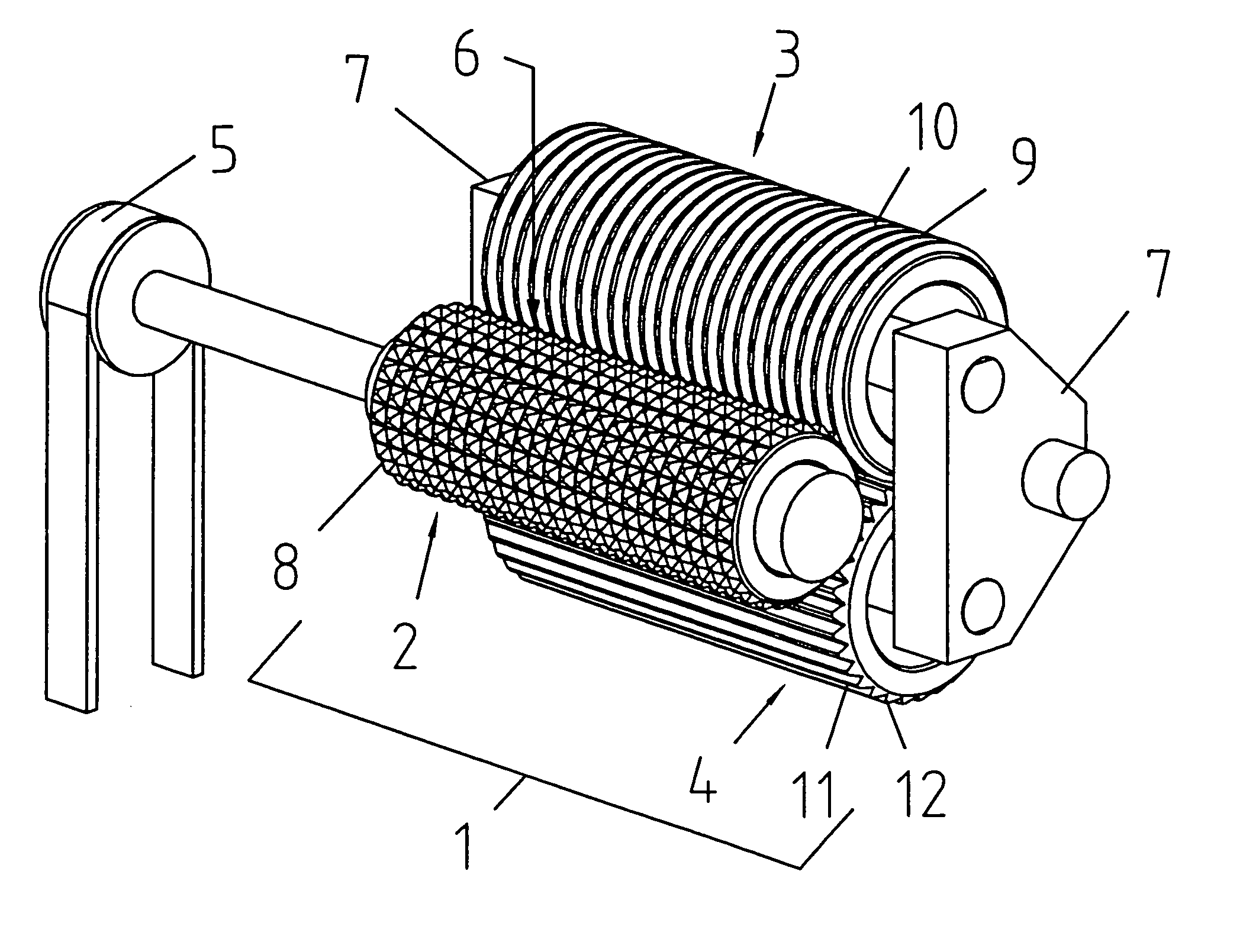
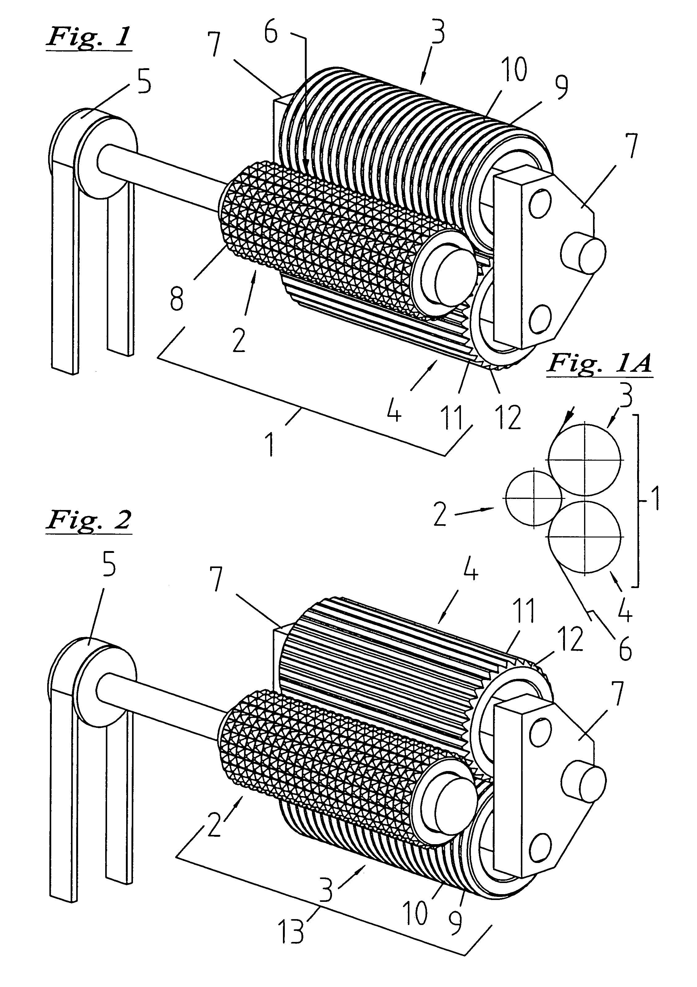
[0032]FIG. 1 shows a first exemplifying embodiment of a device 1 including three embossing rolls where a first embossing roll 2 cooperates with a second embossing roll 3 and a following embossing roll 4, the first roll 2 being driven by a driving system 5 whereas the two other rolls 3 and 4, i.e. the mating rolls, are neither driven nor synchronized with the driven roll by synchronizing elements such as e.g. gearwheels, but driven by the medium 6, see FIG. 1A.

[0033]As symbolically indicated in FIG. 1A, the embossed medium 6, e.g. paper metallized with a thin layer of 0.006 mm, runs in the vertical direction, i.e. from the top to the bottom of the figures.

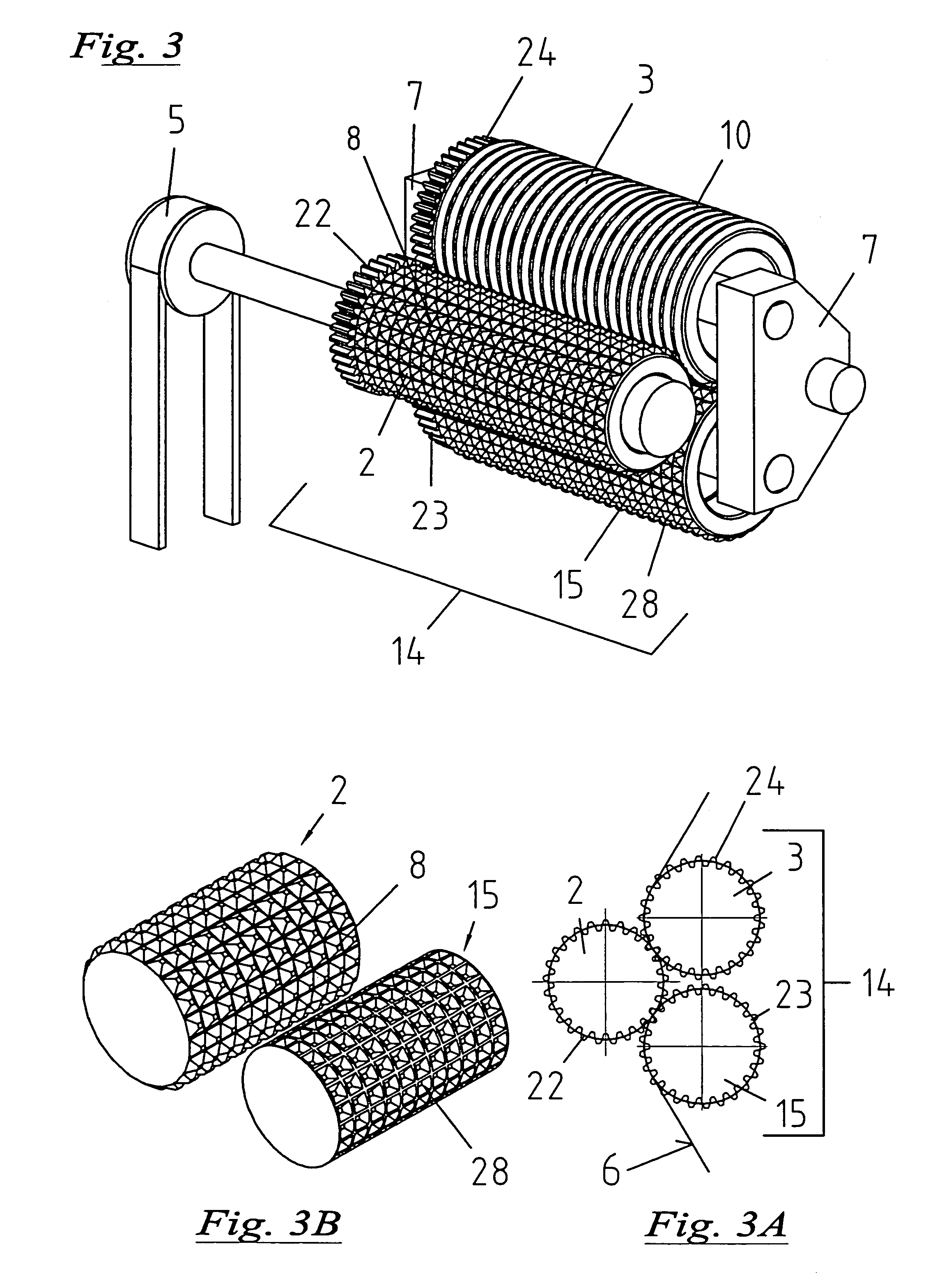
[0034]In contrast to the device disclosed in the mentioned reference WO-A-0 069 622 to the applicant of the present invention, the three embossing rolls do not have the same structure. In the exemplifying embodiment of FIG. 1, the first, driven embossing roll 2 is the same as in the device of the prior art and comprises a number of ...


PUM

PropertyMeasurementUnit
pressureaaaaaaaaaa
dimensionsaaaaaaaaaa
heightaaaaaaaaaa

Abstract

The invention relates to a device for embossing and / or glazing films. The device for embossing includes a first and second embossing roll, through which flat material can be fed under pressure, in order to create a pattern. An additional embossing roll is connected downstream of the second embossing roll, this additional embossing roll interacting with the first or preceding embossing roll. The patterned flat material may be fed between these embossing rolls, in order to be embossed again with essentially the same pattern. In a simplified embodiment, only a total of two rolls are used. In order to achieve as precise an embossing as possible, with special effects, the first driven embossing roll is provided with teeth, while at least one other embossing roll comprises rings or longitudinal ribs, or is smooth.

Description

BACKGROUND OF THE INVENTION[0001](1) Field of the Invention[0002]The present invention refers to a device for the treatment of flat materials, more particularly for embossing and / or satinizing foils, the device comprising at least three embossing rolls.[0003](2) Related Art[0004]A device of this kind is e.g. known from WO-A-00 / 69622, this reference being exclusively referring to rolls having each the same structure, more particularly truncated pyramidal teeth where each tooth of a roll engages between four teeth of another roll while the additional roll has the function of providing an increased embossing quality and a reduced wear of the rolls especially in the case of flat materials having a large paper and small metallized proportion.[0005]The embossing station for embossing fiber webs as for handkerchiefs or toilet paper according to EP-A-1 074 381 comprises a smooth mating roll and two embossing rolls disposed above the latter in a V-shaped arrangement. However, such an arrange...

Claims


Application Information

Patent Timeline
Patent Type & Authority Patents(United States)
IPC IPC(8): B31F1/07B29C59/04B21D22/02B21D22/08B21D33/00
CPCB29C59/04B31F1/07B31F2201/0728B31F2201/0733B31F2201/0753B31F2201/0774B21D31/00
Inventor BOEGLI, CHARLES
Owner BOEGLL GRAVURES SA
Learn More