CNC machine tool

a machine tool and computer numerical control technology, applied in the field of machine tools, can solve the problems of reducing machining precision, waste of energy, and machining chips or other objects jumping or flying into the space between the mains, and achieve the effect of reducing the load of the first, second, and third driving members

Inactive Publication Date: 2006-12-12
CHEN HSI KUAN
View PDF16 Cites 52 Cited by
  • Summary
  • Abstract
  • Description
  • Claims
  • Application Information

AI Technical Summary

Benefits of technology

[0008]According to this invention, a machine tool includes a base having a front portion and a rear portion, and a rotatable worktable including a vertical rotating shaft journalled on the front portion of the base, and a horizontal support plate disposed fixedly on an upper end of the rotating shaft. The support plate has opposite front and rear mounting portions each adapted for mounting a workpiece thereon. The rotating shaft is rotatable so as to exchange positions of the workpieces relative to the base. A support post unit includes a post member disposed fixedly on the rear portion of the base, two vertical Z-axis sliding rails disposed fixedly on the post member and parallel to each other, a vertical first threaded rod journalled in a middle portion of the post member, and a first driving member for driving the first threaded rod to rotate in the post member. A first horizontal rail unit includes a first sliding seat driven by the first threaded rod to move along the Z-axis sliding rails, two horizontal X-axis sliding rails disposed fixedly on the first sliding seat and parallel to each other, a second threaded rod journalled on a middle portion of the first sliding seat, and a second driving member for driving the second threaded rod to rotate on the first sliding seat. A second horizontal rail unit includes a second sliding seat driven by the second threaded rod to move along the X-axis sliding rails, two horizontal Y-axis sliding rails disposed fixedly on the second sliding seat and parallel to each other, a third threaded rod journalled on a middle portion of the second sliding seat, and a

Problems solved by technology

A drawback of the CNC machine tool 100 is that, when the main and auxiliary worktables 13, 16 are spaced apart from each other, machining chips or other objects may jump or fly into a space between the main and auxiliary worktables 13, 16.
If this occurs, it is not possible to move the second workpiece accurately to a predetermined position for machining, thereby reducing machining precision.
Such heavy loads result in waste of energy, and reduces the service

Method used


Image

  • CNC machine tool
  • CNC machine tool
  • CNC machine tool

Examples


Embodiment Construction

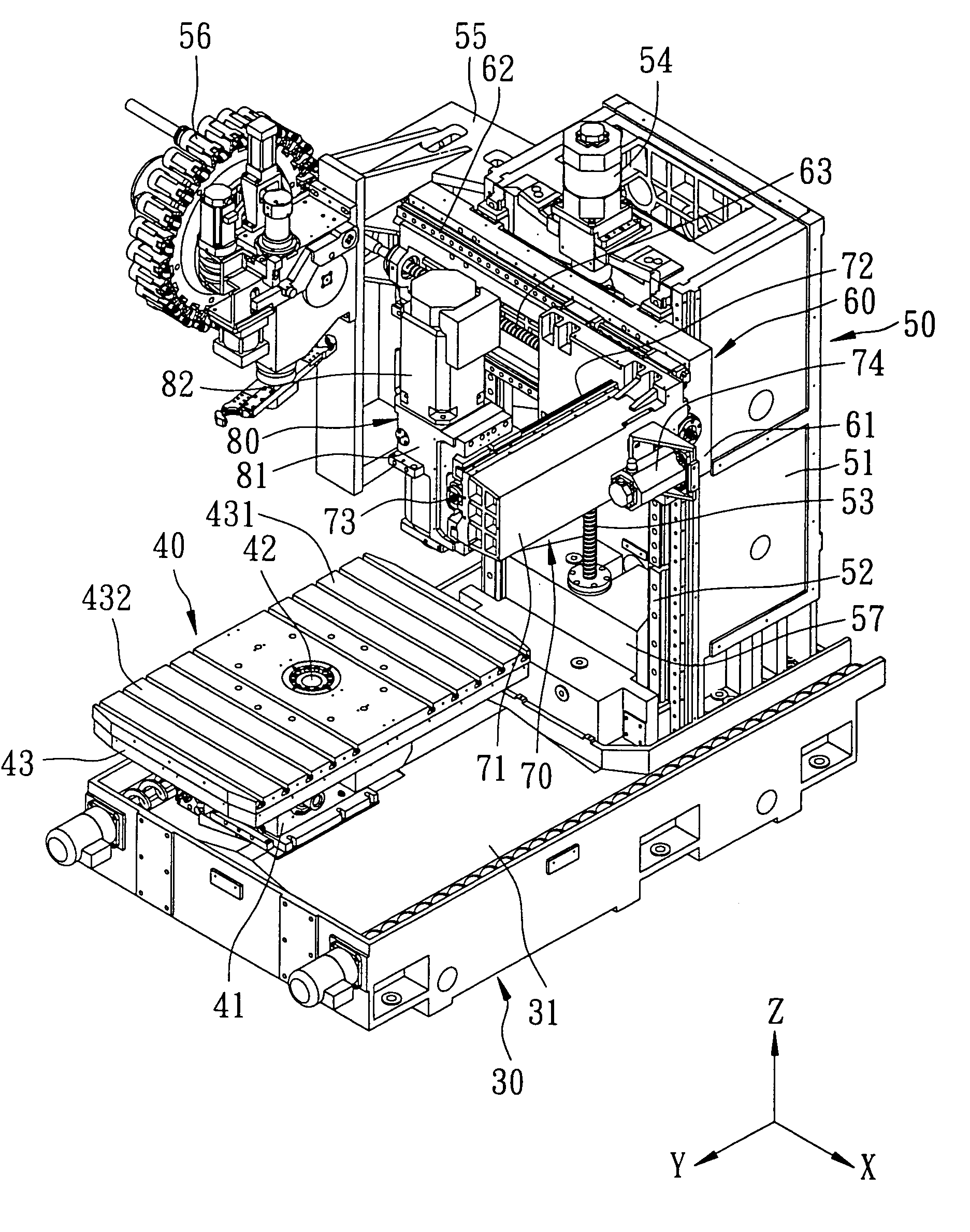
[0022]Referring to FIGS. 3 to 6, the preferred embodiment of a CNC machine tool according to this invention includes a base 30, a rotatable worktable 40, a support post unit 50, a first horizontal rail unit 60, a second horizontal rail unit 70, and a spindle head unit 80.

[0023]The base 30 has a generally rectangular top surface 31.

[0024]The worktable 40 includes a fixed seat 41 disposed fixedly on a front portion of the base 30, a vertical rotating shaft 42 journalled on the fixed seat 41, and a generally rectangular horizontal support plate 43 disposed fixedly on an upper end of the rotating shaft 42. The support plate 43 has opposite front and rear mounting portions 432, 431 each adapted for mounting a workpiece (not shown) thereon. The rotating shaft 42 is rotatable so as to exchange the positions of the workpieces relative to the base 30.

[0025]The support post unit 50 includes a post member 51, two vertical Z-axis sliding rails 52, a first threaded rod 53, a first driving member...


PUM


Abstract

A CNC machine tool includes a worktable supporting two workpieces and rotatable on a base so as to exchange the positions of the workpieces. A post member is fixed on the base. A first horizontal rail unit is movable vertically on the post member. A second horizontal rail unit is movable on the first horizontal rail unit along a first horizontal direction. A spindle head unit is movable on the second horizontal rail unit along a second horizontal direction perpendicular to the first horizontal direction.

Description

BACKGROUND OF THE INVENTION[0001]1. Field of the Invention[0002]This invention relates to a machine tool, and more particularly to a CNC (Computer-Numerical-Controlled) machine tool.[0003]2. Description of the Related Art[0004]Referring to FIG. 1, a conventional CNC machine tool 10 includes a base 11, a sliding seat 12 movable on a front portion of the base 11 along a first horizontal direction (Y), a main worktable 13 movable on the sliding seat 12 along a second horizontal direction (X) perpendicular to the first horizontal direction (Y), a post 14 fixed on a rear portion of the base 11, and a spindle seat 15 movable on the post 14 along a vertical axis (Z). The spindle seat 15 is provided with a spindle 151 for mounting a cutter (not shown). A first workpiece (not shown) is held on the main worktable 13 for machining. An auxiliary worktable 16 is disposed movably on the base 11 for supporting a second workpiece (not shown). After the machining of the first workpiece on the main w...

Claims


Application Information

Patent Timeline
IPC IPC(8): B23Q3/157B23C1/06B23Q1/56B23Q11/00
CPCB23C1/06B23Q1/626B23Q1/66Y10T29/5196Y10T409/309576Y10T409/30532Y10T483/176Y10T483/1755Y10T409/309688Y10T483/1748Y10T483/16Y10T408/92Y10T483/1736
Inventor CHEN, HSI-KUAN
Owner CHEN HSI KUAN
Why Eureka
Try Eureka