
Infusion device with needle shield

a technology of infusion device and needle shield, which is applied in the field of infusion device with needle shield, to achieve the effect of simple and cost-effective, high degree of protection against injury

Inactive Publication Date: 2006-12-12
UNOMEDICAL AS
View PDF441 Cites 77 Cited by
  • Summary
  • Abstract
  • Description
  • Claims
  • Application Information

AI Technical Summary

Benefits of technology

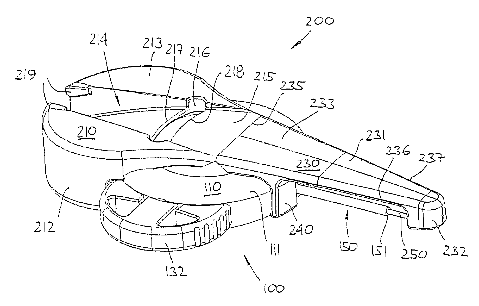
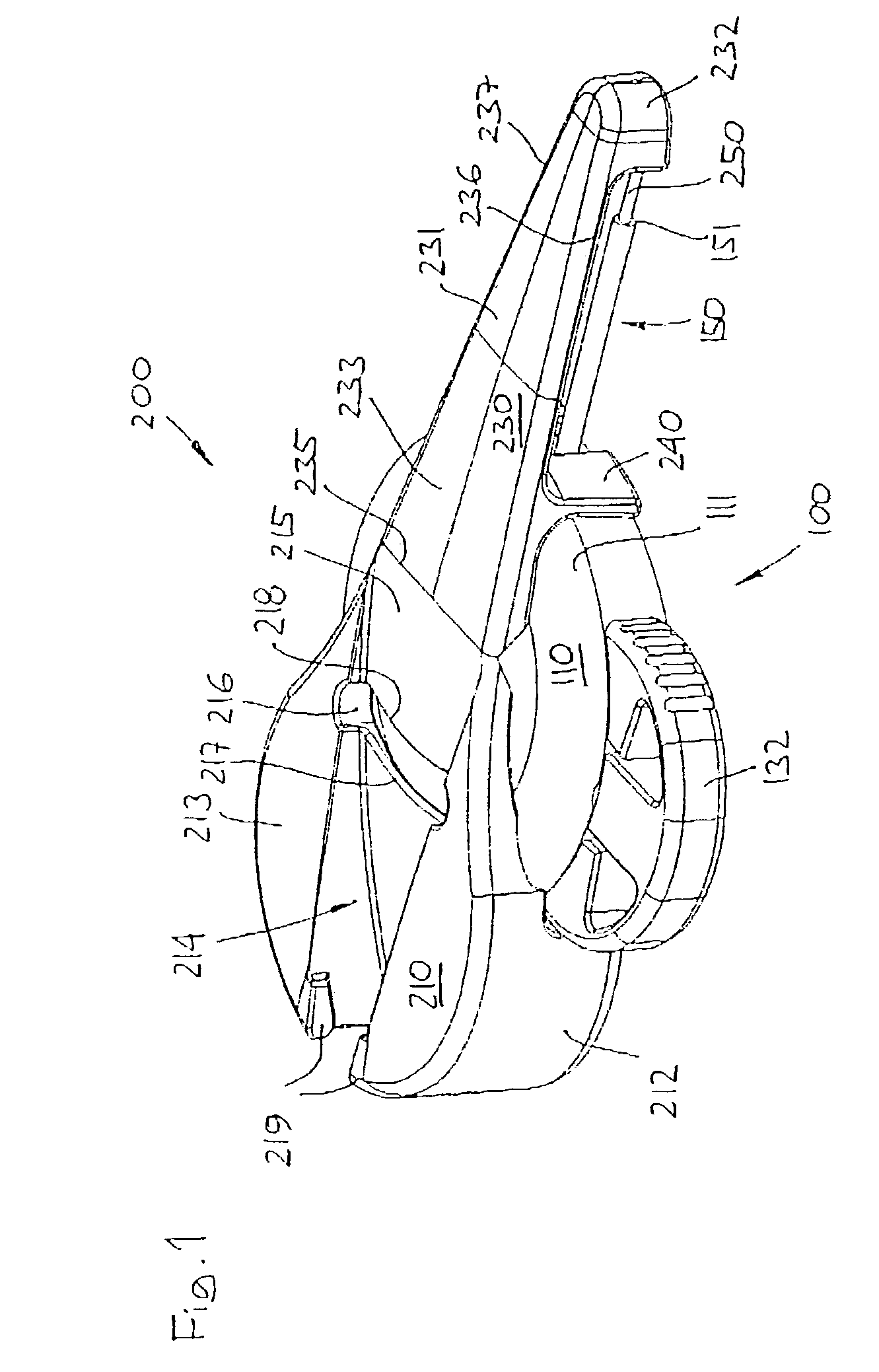
[0012]Having regard to the above discussion of the prior art, the object of the present invention is to provide an infusion device comprising a hollow cannula and having an insertion needle arranged there through, in which shielding means is incorporated providing a user with a high degree of protection against injury from unintended needle prick during operation and handling of the device yet providing ease of use as well as allowing the device to be manufactured in a simple and cost effective manner.
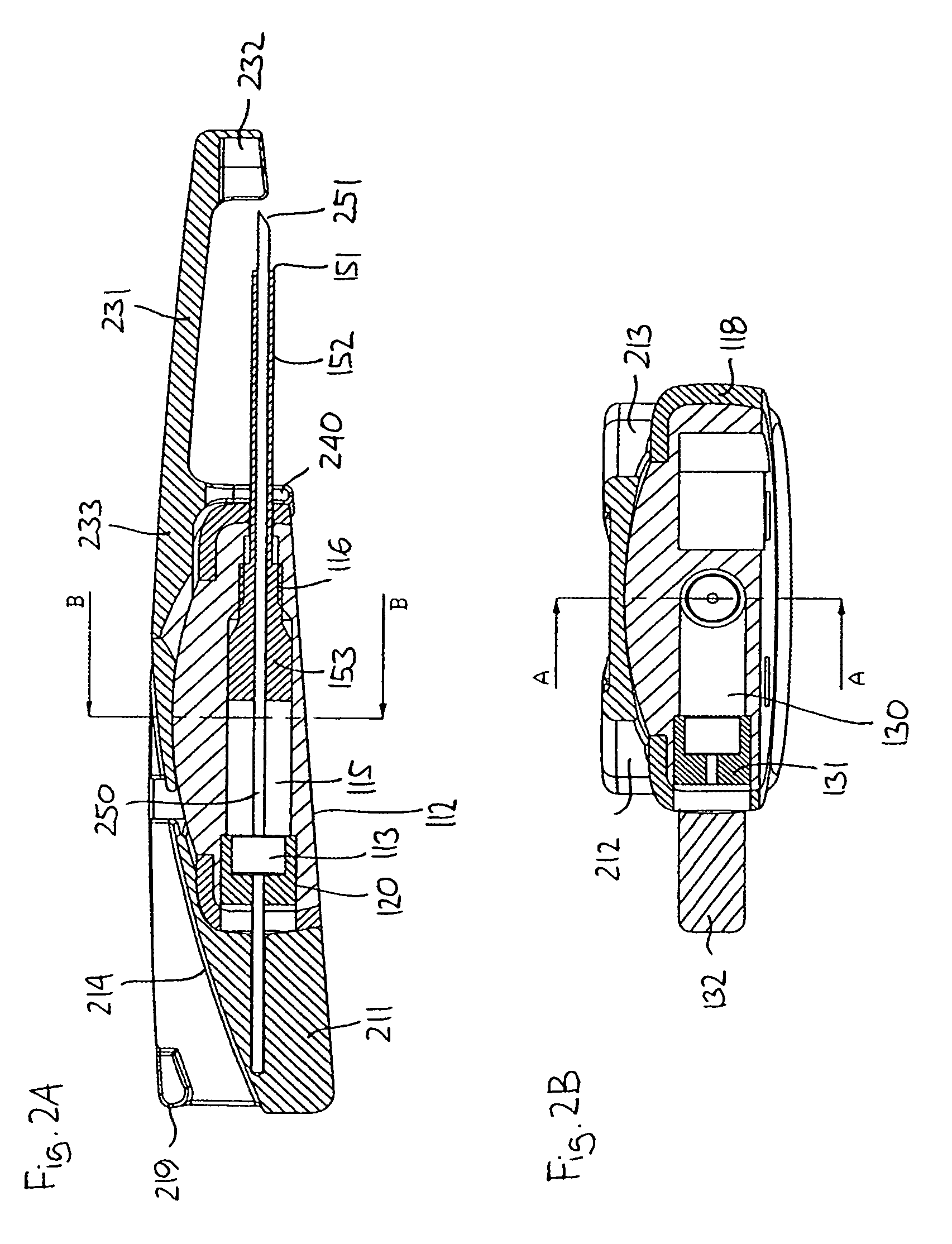
[0015]The final position may be identical with the initial position, or it may be different as in a preferred embodiment in which the needle is bend when the shield member and the hub is locked together, whereby the bend needle provides a biasing effect between cooperating locking means on the shield part and the handle part, and whereby the bend needle closely abuts on the shield to ensure that unintended contact with the needle is avoided.

Problems solved by technology

The use of insertion needles, or needle devices in general, is associated with some disadvantages during use thereof due to the potential danger of exposure to the pointed tip before use as well as after the needle has been withdrawn and before it has been properly discarded.

Method used


Image

  • Infusion device with needle shield
  • Infusion device with needle shield
  • Infusion device with needle shield

Examples


second embodiment

[0050]Next, use of the device corresponding to the second embodiment will be described. In order to insert the cannula with the needle arranged there through, the shield member 430 is pivoted backwardly towards the hub 410 approximately 160 degrees as shown in FIG. 7, thereby positioning the shield member in the retracted position allowing the cannula to be inserted, see FIG. 7. As appears, the shield member pivots corresponding to a first hinge member 436 of the zigzag portion. As shown, the shield member is positioned and locked in place along a side portion of the hub by a flange 431 being gripped by a corresponding slot (not shown) in the hub thereby holding it releasably in place, this providing for improved handling during the insertion procedures.

[0051]After the cannula has been placed, the insertion device is withdrawn from the infusion device and the shield member is disengaged from the hub and “pivoted” to a final position covering the needle, see FIG. 8. As appears, the s...

first embodiment

[0052]As in the first embodiment, the needle is bend when the shield member and the hub is locked together, the bend needle providing a biasing effect between the locking means.

[0053]While the present invention has been described in connection with the preferred embodiment shown in the various figures, it is to be understood that other similar embodiments may be used or modifications and additions may be made to the described embodiment for performing the same function of the present invention without deviating there from. For example, the shield may be provided by two or more members connected to each other, just as the means allowing the shield member to move between the different positions relative to the hub may be provided by e.g. a telescoping arrangement instead of one or more hinges.


PUM


Abstract

The invention relates to a medication infusion set of the type having a flexible cannula adapted for subcutaneous placement, in combination with an insertion, or puncturing, device comprising an insertion needle extending through the cannula and beyond the outer tip thereof, the insertion device further comprising a shield adapted to cover the insertion needle when the latter is withdrawn from the cannula. More specifically, the invention provides a fully integrated shield member having a position in which it covers the cannula and the needle when the insertion device is connected to the housing, a position allowing the cannula to be inserted when the insertion device is connected to the housing, and a position in which the shield covers the needle and the outer tip thereof when the insertion device has been removed from the housing. By this arrangement the need for a separate cover to protect the needle prior to use can be dispensed with.

Description

[0001]This application claims priority to Danish Application PA 2002 00208, filed Feb. 12, 2002, the entirety of this reference is incorporated herein.FIELD OF THE INVENTION[0002]The invention relates generally to devices for delivering a selected medication or another therapeutic fluid to a patient at a subcutaneous or other infusion site. More particularly, the invention relates to a medication infusion set of the type having a flexible cannula adapted for subcutaneous placement, in combination with an insertion, or puncturing, device comprising an insertion needle extending through the cannula and beyond the outer tip thereof, the insertion device further comprising a shield adapted to cover the insertion needle when the latter is withdrawn from the cannula.BACKGROUND OF THE INVENTION[0003]Medication injection or infusion sets are generally well known in the art, to include a relatively soft and flexible cannula providing a transcutaneous pathway through which a selected medicati...

Claims


Application Information

Patent Timeline
IPC IPC(8): A61M5/178A61M25/06
CPCA61M25/0631Y10S128/919
Inventor MATHIASEN, ORLA
Owner UNOMEDICAL AS
Learn More