Auto-deep scan for capacitive sensing

a capacitive sensing and deep scan technology, applied in the field of electromechanical sensors, can solve the problems of reducing the ability to accurately determine the centerline of the stud, and affecting the accuracy of the stud. effect of reducing the effect of an unknown thickness of the member

Active Publication Date: 2006-12-12
ZIRCON
View PDF44 Cites 33 Cited by
  • Summary
  • Abstract
  • Description
  • Claims
  • Application Information

AI Technical Summary

Problems solved by technology

Finding studs is a typical problem for building repairs, picture hanging, etc.
While this procedure is effective in determining the centerline of a stud, significant errors in determining the location of the stud's edges can occur.
The ballooning may be asymmetric due to electrical wires, metallic pipes and other objects in close proximity to the stud, which in turn may lead to a reduced ability to accurately determine a stud's centerline.
Unfortunately, using a dual sensitivity control only partially minimizes the ballooning effect.
The above methods, which use electronic wall stud sensors, are unable to reliably and accurately sense an edge of a stud (or other structural member) through surfaces that are thicker than 38 mm (1½ inches).
Additionally, these sensors, if overly sensitive, falsely indicate the presence of non-existing studs.
Therefore, known sensors have disadvantages.

Method used


Image

  • Auto-deep scan for capacitive sensing
  • Auto-deep scan for capacitive sensing
  • Auto-deep scan for capacitive sensing

Examples


Embodiment Construction

[0023]In the following description, reference is made to the accompanying drawings which illustrate several embodiments of the present invention. It is understood that other embodiments may be utilized and mechanical, compositional, structural, electrical, and operational changes may be made without departing from the spirit and scope of the present disclosure. The following detailed description is not to be taken in a limiting sense, and the scope of the embodiments of the present invention is defined only by the claims of the issued patent.

[0024]Some portions of the detailed description which follows are presented in terms of procedures, steps, logic blocks, processing, and other symbolic representations of operations on data bits that can be performed on computer memory. A procedure, computer executed step, logic block, process, etc., are here conceived to be a self-consistent sequence of steps or instructions leading to a desired result. The steps are those utilizing physical ma...


PUM


Abstract

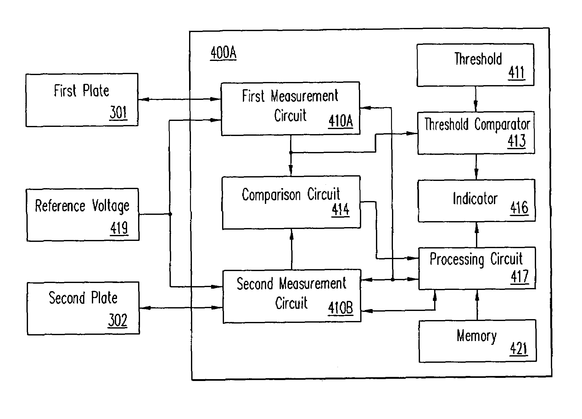
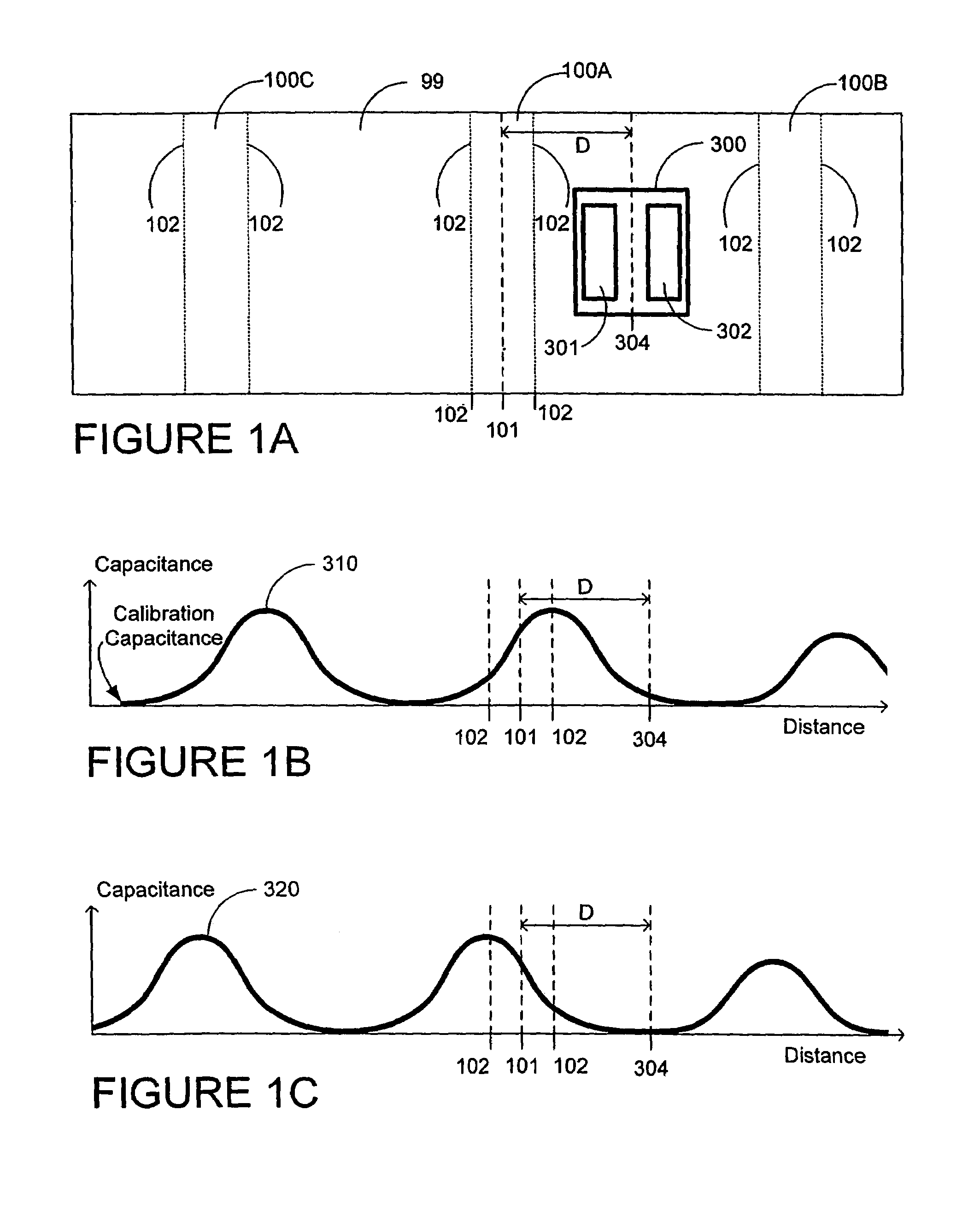
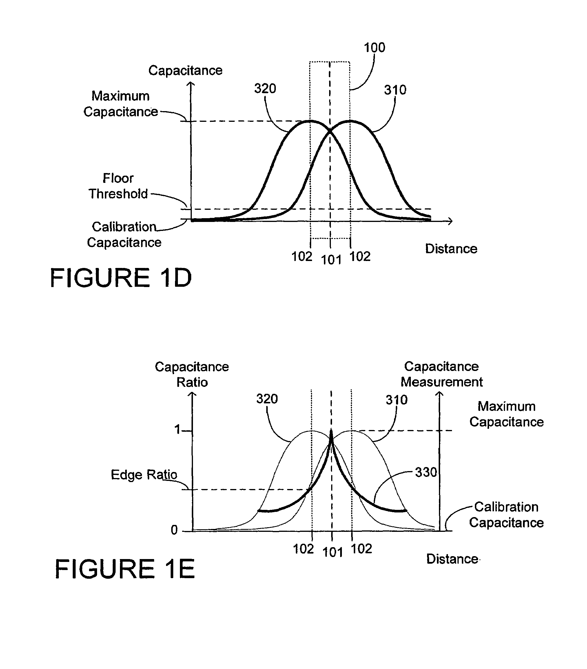
A stud or joist sensor and associated sensing method using an amplitude and a ratio of capacitance measurements from a plurality of capacitive sensing elements. The sensor locates a feature of an object or discontinuity behind a surface or wall, such as an edge and / or a center of a stud behind the surface, a joist under a floorboard, a gap behind sheetrock, a metal conductor behind a surface or the like. The sensor may be moved over the surface, thereby detecting changes in capacitance. The change in capacitance is due to the effective dielectric constant caused by the passage over a hidden object such as a stud. When two capacitive sensing elements provide equivalent capacitance measures, the sensor is over a centerline of the stud. When a ratio of the capacitance measurements equals a transition ratio, the sensor is over an edge of the stud. When the sensor is over the stud and the capacitance measurements are low, the sensor is over a deep stud.

Description

BACKGROUND OF THE INVENTION[0001]1. Field of the Invention[0002]This invention relates to an electronic sensor, and, in particular, to a sensor suitable for detecting the location of an object behind a variety of surfaces, such as walls, floors and other non-electrically conductive structures (but not limited to building structures). More specifically, the invention relates to an electronic sensor useful to detect centerlines and edges of wall studs, floor joists, and the like.[0003]2. Description of the Prior Art[0004]U.S. Pat. No. 4,464,622 entitled “Electronic wall stud sensor,” issued Aug. 7, 1984, and incorporated in its entirety by reference herein, discloses an electronic wall stud sensor particularly suitable for locating a stud positioned behind a wall surface. (A “stud” is a structural member of a building to which an interior wall surface such as wall board or paneling is affixed.) Typically in the U.S., “2-by-4” wooden studs are used in construction. Nominally, a 2-by-4 ...

Claims


Application Information

Patent Timeline
Patent Type & Authority Patents(United States)
IPC IPC(8): G01R27/26G01R19/00G01V3/08
CPCG01V3/088
Inventor MILLER, LAWRENCE F.
Owner ZIRCON
Why Eureka
Try Eureka