Disk drive implementing wear prevention in a high frequency access band of tracks

a wear prevention and high frequency access technology, applied in the field of disk drives, can solve the problems of wear in the high frequency access band of tracks, damage and data loss, and the lubricating film that covers the disk surface is not enough, so as to facilitate wear prevention

Active Publication Date: 2006-12-12
WESTERN DIGITAL TECH INC
View PDF7 Cites 145 Cited by
  • Summary
  • Abstract
  • Description
  • Claims
  • Application Information

AI Technical Summary

Benefits of technology

[0013]The present invention may also be regarded as a method of operating a disk drive comprising a disk having a plurality of tracks, and a head actuated over the disk. An access command is received from a host, wherein the access command identifies at least one of the t

Problems solved by technology

However, decreasing the fly-height can deplete the lubricating film that covers the disk surface, particularly if the head remains at the same radial location over an extended period of time.
Thi

Method used


Image

  • Disk drive implementing wear prevention in a high frequency access band of tracks
  • Disk drive implementing wear prevention in a high frequency access band of tracks
  • Disk drive implementing wear prevention in a high frequency access band of tracks

Examples


Embodiment Construction

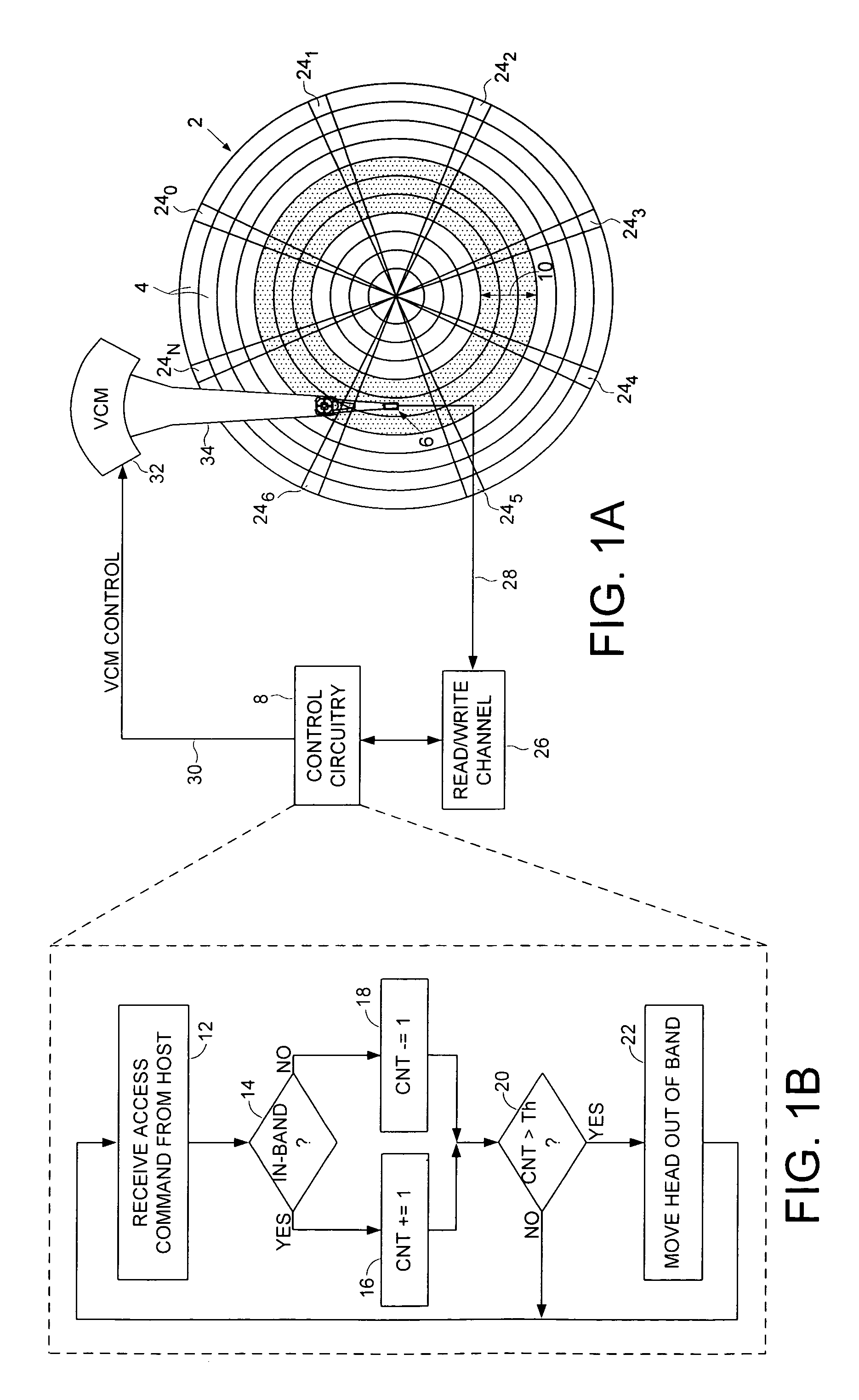
[0022]FIG. 1A shows a disk drive according to an embodiment of the present invention comprising a disk 2 having a plurality of tracks 4, a head 6 actuated over the disk 2, and control circuitry 8 for servicing an access command received from a host, wherein the access command identifies at least one of the tracks 4. The control circuitry 8 identifies a band of tracks 10 associated with the access command, maintains a counter for tracking an amount of time the head is within the band of tracks 10, and moves the head 6 out of the band of tracks 10 in response to the counter to facilitate wear prevention.

[0023]FIG. 1B is a flow diagram executed by the control circuitry 8 for performing the wear prevention according to an embodiment of the present invention. At step 12 the control circuitry 8 receives an access command from the host for servicing. If while servicing the access command at step 14 the head 6 is within the band of tracks 10, at step 16 the counter is incremented, otherwise...


PUM


Abstract

A disk drive is disclosed comprising a disk having a plurality of tracks, a head actuated over the disk, and control circuitry for servicing an access command received from a host, wherein the access command identifies at least one of the tracks. The control circuitry identifies a band of tracks associated with the access command, maintains a counter for tracking an amount of time the head is within the band of tracks, and moves the head out of the band of tracks in response to the counter to facilitate wear prevention.

Description

BACKGROUND OF THE INVENTION[0001]1. Field of the Invention[0002]The present invention relates to disk drives for computer systems. More particularly, the present invention relates to a disk drive implementing wear prevention in a high frequency access band of tracks.[0003]2. Description of the Prior Art[0004]In disk drives, a head is actuated radially over a disk in order to access a target track recorded on the disk. The head is attached to a distal end of an actuator arm which is rotated about a pivot by a voice coil motor during seek operations. As the disk rotates, an air bearing forms which causes the head to “fly” just above the disk surface while writing magnetic transitions during a write operation, or reading the magnetic transitions during a read operation. The head comprises a slider having an air bearing surface and an integrated transducer, such as a write coil and a magnetoresistive read element.[0005]Decreasing the distance between the transducer and disk surface (fly...

Claims


Application Information

Patent Timeline
IPC IPC(8): G11B21/02G11B5/596
CPCG11B5/255G11B5/3106G11B5/54G11B5/5526
Inventor COKER, KENNY T.ROTHBERG, MICHAEL S.HANSON, DANIEL A.VALLIS, MARK F.DANG, QUOC N.
Owner WESTERN DIGITAL TECH INC
Why Eureka
Try Eureka